Sony EVID70P driver and firmware


Related Sony EVID70P Manual Pages
Download the free PDF manual for Sony EVID70P and other Sony manuals at ManualOwl.com
Technical Manual - Page 4

... to more than one camera)
Computer, TV or VCR with a video input jack
to VISCA RS-422 2)
AC power adaptor MPA-AC1 (supplied)
to AC outlet
to DC IN 12V
Power cord (supplied)
1) When the camera is connected to a computer with a VISCA cable (cross type, RS-232C), you can operate the camera with the computer. To obtain a cable, consult the dealer...
Technical Manual - Page 5

... Controls
Locations of Controls
Main Unit
Front
12
Rear
34 56 7 8
Bottom
qf qg
9 q; qa qs qd
1 Lens A wide conversion lens can be attached.
2 Sensor for the Remote Commander 3 POWER lamp 4 STANDBY lamp 5 Sensor for the Remote Commander 6 IMAGE FLIP switch
Flips the image upside down and executes Pan/Tilt movement according to the camera installation. Normally set...
Technical Manual - Page 9

...set, the speed can be 1/30, 1/15, 1/8, or 1/4 s. The picture output is read at a normal rate from the memory. The memory is updated...8
02
4
01 a)
2
00 a)
1
a) For AE-Manual only.
PAL 10000 6000 3500 2500 1750 1250 1000
600 425 ...set by the user. Exposure is controlled by gain when dark and by iris when bright. As both gain and iris are fixed, this mode is used when exposing at a fixed camera...
Technical Manual - Page 11

... Commands and POWER of the Remote Commander; the display and other features are turned off.
I/F clear Clears the Command buffer of the camera. Clearing the buffer can also be carried out from the control application software when the power is on.
Address set VISCA is a protocol, which normally can support a daisy chain of up to seven attached devices. Therefore, whenever a camera is...
Technical Manual - Page 16

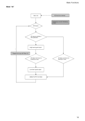
Mode "01"
Alarm On AE moves.
Basic Functions
Focus Position into memory Hysteresis is set to the factory preset.
Focus moves outside of the hysteresis.
*
High level signal output
* Repeat this loop until Alarm off.
AE does not move for a period of time.
AE does not move for a period of time.
Low level signal output Update the Focus position data.
16
Technical Manual - Page 18
Mode "03"
Alarm On AE moves.
AE moves outside of the hysteresis.
High level signal output * * Repeat this loop until Alarm off.
AE does not move for a period of time.
Low level signal output Update the AE level data
Basic Functions
AE level into memory Hysteresis is set to the factory preset.
AE does not move for a period of time.
18
Technical Manual - Page 31

... to the controller via the peripheral devices. The devices on the network are assigned addresses.
The address of the controller is fixed at 0. The addresses of the peripheral devices are 1, 2, 3 ... in order, starting from the one nearest the controller. The address of the peripheral device is set by sending address commands during the initialization of the network. The VISCA devices each have...
Technical Manual - Page 35

... outputs the signals of the Remote Commander at 0 to 5 V when the IR OUT switch is set to ON.
• EVI-D70/P
1. DTR 2. DSR 3. TXD 4. GND 5. RXD 6. GND 7. IR OUT 8. N.C.
Command List
Windows D-sub 9 pin 1. CD 2. RXD 3. TXD 4. DTR 5. GND 6. DSR 7. RTS 8. CTS 9. RI
EVI Camera or Mini DIN 8 pin serial 1. DTR 2. DSR 3. TXD 4. GND 5. RXD...
Technical Manual - Page 59

...(2 1/4 × 1 1/16 × 8 3/8 in.) (w/h/d)
EVI-D70P: 1/1 to
(excluding protruding parts)
1/10,000 s (VISCA control)
Mass
Video camera:
Horizontal resolution
950 g (2 lb 2 oz.)
NTSC : 470 TV (WIDE end)
Remote Commander: 190 g (3.8 oz.)
PAL : 460 TV (WIDE end)
Installation angle
Video S/N
50 dB
±15 degrees to a horizontal surface
Pan/tilt action
Horizontal: ±170 degrees...
Technical Manual - Page 61

...
Use of the demonstration software developed by Sony Corporation or use of the software with customer developed application software may damage hardware, the application program or the camera. Sony Corporation is not liable for any damages under these conditions.
Operation
Start the camera control software on your computer after you turn on the camera and the image is displayed.
Other
Do not...
Operating Instructions - Page 31

... an experienced radio/TV technician for help.
You are cautioned that any changes or modifications not expressly approved in this manual could void your authority to operate this equipment.
The shielded interface cable recommended in this manual must be used with this equipment in order to comply with the limits for a digital device pursuant to Subpart...
Operating Instructions - Page 33

...
Overview
Features 34 Supplied Accessories 34 Locations of Controls 36
Main Unit 36 Remote Commander 37
Basic Operations
Preparations 39 Installation 39 Installing the unit on the ceiling .40 Connections 43 Turning on the Power 44
Pan/Tilt Operation 45 Adjusting the Camera 47 Having the Camera Memorize the Setting - Presetting feature 48
General
Troubleshooting 49 Precautions 49...
Operating Instructions - Page 38

5 L/R DIRECTION SET button (45)
6 POWER switch (44)
7 BACK LIGHT button (47)
8 POSITION buttons (48) Numeric buttons (Button 1 also works as the STD button. Button 2 also works as the REV button.) (45) PRESET button RESET button
9 PAN-TILT RESET button (45)
0 ZOOM buttons (47) SLOW T button SLOW W button FAST T button FAST W button
Installing batteries
R6...
Operating Instructions - Page 39

... Operations
Preparations
Installation
Be sure to place the main unit on a flat surface. If you must place the camera on an inclined surface, make sure the incline is less than ±15 degrees.
Notes
• Do not grasp the camera head when carrying the video camera.
• Do not turn the camera head manually. Doing so...
Operating Instructions - Page 40

... direction in which the camera will shoot, make the required holes for the junction box, and connecting cables.
Note
The connecting cables cannot be passed through ceiling bracket (A). A hole for the wiring is required in the ceiling at the back of the unit where it is attached to the ceiling.
Installation
1 Set the IMAGE FLIP...
Operating Instructions - Page 42

... position 1.
Ceiling
Note
Take the proper steps to ensure that the load of the cables connected does not cause problems.
Removing the camera
1 Remove the 3 screws used to attach
the camera in step 6 of "Installation."
2 While pushing the entire camera up
towards the ceiling, move the camera to the front. The hooks will disengage, and you can...
Operating Instructions - Page 44

... an S-Video input connector. You might not be able to use your existing computer with your Color Video Camera unless you provide the computer with a video capture board and/ or software. Consult your computer dealer or manufacturer for details.
• Use only the AC power adaptor (MPAAC1) supplied with the unit. Do not use any other AC...
Operating Instructions - Page 51

... g (3.8 oz.)
Installation angle
±15 degrees to a horizontal surface
Supplied accessories
AC power adaptor (1) AC power cord (1) Remote Commander (1) Ceiling bracket (A) (1) Ceiling bracket (B) (1) Wire rope (1)
Screw 3M 3 × 6 (6)
Operating Instructions (1)
Design and specifications are subject to change without notice.
...* Maximum speed settings with VISCA control.
Specifications 51...