Sony BRCH700 - CCTV Camera driver and firmware
Drivers and firmware downloads for this Sony item
Related Sony BRCH700 Manual Pages
Download the free PDF manual for Sony BRCH700 and other Sony manuals at ManualOwl.com
Operating Instructions - Page 2

... electrical shock, do not open the cabinet. Refer servicing to qualified personnel only.
WARNING Use the Sony MPA-AC1 AC power adapter provided with this equipment as a power supply source. Any other power sources may result in hazards such as a fire. This product has no power switch. Disconnect device of this equipment is the mains plug of the...
Operating Instructions - Page 4

Adjusting the Brightness 47 Storing the Camera Settings in Memory - Presetting Feature 48
Storing Camera Settings 48 Setting the Speed of the Camera Moving to a
Preset Position 49
Installation and Connections
Installation 50 Removing/Attaching the Cable Cover 50 Attaching an Interface Board 50 Installing the Camera 51 Installing the Camera in a High Position ........ 52
Connections 57 ...
Operating Instructions - Page 6

... HD Optical Multiplex Card. Use of these interface boards gives the camera the capability of having various image output formats.
Long-distance image transmission and pan/tilt/zoom control
• Combined use of the BRBK-H700 HD Optical Multiplex Card, CCFC-M100HG Optical Fiber Cable and BRU-H700 Optical Multiplex Unit, and Sony's unique camera connection technology and optical digital multiplex...
Operating Instructions - Page 19

... output.
5 Camera address selectors Set the address of the camera. Normally set to "0". With this setting, addresses are assigned to the cameras automatically in the connected order by pressing the POWER button while holding down the RESET button on the RMBR300 Remote Control Unit. You can assign the camera address "1" to "7" manually by setting these selectors as follows:
Camera address Switch...
Operating Instructions - Page 20

... (supplied)
1 2 3
4
5
POWER
CAMERA SELECT
1
2
3
AUTO
FOCUS MANUAL
FAR NEAR
DATA SCREEN
BACK LIGHT
STD REV
123
456
PRESET
RESET
POSITION
PAN-TILT
HOME
PAN-TILT RESET
SLOW ZOOM FAST
TT
W
L/R DIRECTION SET
W
RM-EV100
6
7 8
9 q;
A CAMERA SELECT buttons Press the button corresponding to the camera you want to operate with the Remote Commander. The camera number can be set using...
Operating Instructions - Page 21

... operations of the RM-BR300 Remote Control Unit when it is used with BRC-H700 cameras. For operations with other cameras, refer to the Operating Instructions supplied with the RM-BR300.
Front
890qaqsqd qf
1 2
3 4
5 6 7
VALUE
LOCK
-
+
R
BRIGHT
MODE
-
+
B
FOCUS
AUTO
AUTO MANUAL
NEAR
FAR
ONE PUSH AF
RESET PRESET
SHIFT L/R
DIRECTION
POWER
PANEL LIGHT
BLACK PAN-TILT...
Operating Instructions - Page 24

... of the audio line signal input from the AUDIO IN jacks on the BRBK-H700 HD Optical Multiplex Card inserted into the camera via the Optical Fiber Cable.
F ~AC IN connector Connect the supplied AC power cord.
G CAMERA connector Connect to the optical connector of the BRBKH700 HD Optical Multiplex Card installed in the BRC-H700 camera using the CCFC-M100HG Optical Fiber Cable. A dustproof cap...
Operating Instructions - Page 36

... Menu
The DOWN CONVERTER menu is displayed only when the HFBK-SD1 SD Interface Board is inserted into the card slot of the camera.
>D-SUB OUT1
YPbPr
D-SUB OUT2
VBS
IMG SIZE 16:9[LETTER]
SETUP
OFF
The STATUS menu consists of PAGE1 to PAGE5. This menu only displays the current menu settings, and you cannot change them...
Operating Instructions - Page 39

... on the Remote Commander. When you turn the power off using the Remote Commander, the POWER lamp turns off and the STANDBY lamp lights on the camera.
POWER
CAMERA SELECT
1
2
3
AUTO
FOCUS MANUAL
FAR NEAR
DATA SCREEN
BACK LIGHT
POWER
STANDBY lights.
Pan/Tilt and Zoom Operation
Panning and Tilting
STD
POWER
1
CAMERA
SELECT 2
1
FOCUS
3
MANUAL NEAR
BACK
LIGHT
CAMERA SELECT
FAR...
Operating Instructions - Page 43

.... Then you can switch the camera to be controlled simply by pressing the corresponding CAMERA button.
To assign camera addresses automatically
1 Make sure that the camera address selector on the
bottom of each camera is set to "0."
For setting the camera address selector, see page 19.
2 Turn on the power of all the connected cameras and
the RM-BR300 Remote Control Unit.
43 Turning on the...
Operating Instructions - Page 50

...
1 2 3 IR SELECT
OFF ON DATA MIX
RGB/COMPONENT
Attaching an Interface Board
Attach an interface board (not supplied) to the card slot on the rear of the camera.
1 Loosen the two screws to remove the card slot
cover.
2 Hold the lower ends of the cable cover and pull it
toward you.
1 2 3 4 5 6 7 8 9
VISCA RS-422
OFF
ON...
Operating Instructions - Page 51
... two screws on the interface board and pull the board out straight and slowly.
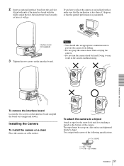
Installing the Camera
To install the camera on a desk
Place the camera on a flat surface.
To attach the camera to a tripod
Attach a tripod to the screw hole used for attaching a tripod on the bottom of the camera. The tripod must be set up on a flat surface...
Operating Instructions - Page 52

...; The ceiling bracket cannot be attached to the junction box when installing the camera on a ceiling.
Installation on a ceiling (example)
1 Remove the cable cover on the rear of the camera.
For details on how to remove it, see "To remove the cable cover" on page 50.
2 Set IMG-FLIP to ON in the SYSTEM menu. 3 Remove the...
Operating Instructions - Page 53
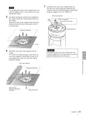
...other screws may damage the camera.
5 Attach the attachment materials (not supplied) to
the ceiling bracket (B), and install the bracket on the ceiling. Align the f hole on the ceiling bracket (B) in the direction where the front of the camera will be positioned later.
Attachment... of the wire rope.
M5 (3/16 inch) hexagon socket head cap screw
Ceiling bracket (B)
Installation and Connections
53...
Operating Instructions - Page 54

... to ensure that the load of the cables connected does not cause problems.
11 Attach the cable cover.
For attachment, see page 50. The SONY and/or HD nameplates can be turned upside down, if necessary.
To remove the camera
1 Remove the three screws used to attach the camera
in step 9 of "Installation on a ceiling (example)."
2 Turn...
Operating Instructions - Page 55

...a shelf, etc. on
which the camera is to be installed. Use four screws (not supplied) ...camera.
4 Attach the supplied wire rope to the ceiling bracket
(A). Pass the wire rope through the fixing hole and attach its end to the attachment hole on the bracket using the supplied one screw (3M4 × 8).
Wall f hole
Screws (4)
Ceiling bracket (B)
Shelf, etc.
Hole for connecting cables
55 Installation
Operating Instructions - Page 56

...rope to the material independent of the shelf, etc. where the ceiling bracket (B) is attached.
Ceiling bracket (A)
Align.
Installation and Connections
Wire rope (supplied)
Ceiling bracket (B)
8 Secure the ceiling brackets (A) and (B) using the
supplied three screws... attach them by turning the ceiling bracket (A) with the camera counterclockwise.
56 Installation
3M3 × 8 (supplied)
Operating Instructions - Page 57
...
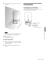
Connecting to an AC Outlet
Use the supplied AC power adaptor and AC power cord to connect the camera to an AC outlet.
Installation and Connections
Note
Take the proper steps to ensure that the load of the cables connected does not cause problems.
10 Attach the cable cover.
For attachment, see page 50.
To remove the...
Operating Instructions - Page 58

... plugs, see back cover.
RS-232C cable*
Installation and Connections
VISCA RS-232C
RM-BR300 Remote Control Unit DC IN 12V
AC power cord*
to AC outlet AC power adaptor*
* supplied with the RM-BR300...camera (page 19) and the DIP switch on the bottom of the Remote Control Unit (page 23) are set to RS-232C.
to AC outlet VISCA RS-422
VISCA RS-422 cable
VISCA RS-422
RM-BR300 Remote Control...
Operating Instructions - Page 59

... Equipped with the Analog Component (YPbPr) Input Connector
Connecting a Device Equipped with VISCA RS-232C Connector
Connections with the VISCA RS-232C cables (cross type) enable control of multiple cameras with a single RM-BR300 Remote Control Unit.
Installation and Connections
to AC outlet
RGB/COMPONENT Connecting cable with D-sub 15-pin connectors (commercially available) to component video...