Sony BRC300 driver and firmware

Related Sony BRC300 Manual Pages
Download the free PDF manual for Sony BRC300 and other Sony manuals at ManualOwl.com
Operating Instructions - Page 2
... your authority to operate this equipment. The shielded interface cable recommended in this manual must be used with this equipment in order to comply with the limits for a computing device pursuant to Subpart B of Part 15 of FCC Rules. For the customers in Canada This Class A digital apparatus complies with Canadian ICES-003. Pour les...
Operating Instructions - Page 4

... Card ...42 Installing the Camera ...42 Installing the Camera on the Ceiling ...43 Connections ...46 Connecting to an AC Outlet ...46 Connecting the RM-BR300 Remote Control Unit ...47 Connecting a Video Monitor, VTR, etc. Equipped with the Composite Video Input Connector ...48 Connecting a Video Monitor, VTR, etc. Equipped with the S-Video Input Connector ...48 Connecting a Device Equipped...
Operating Instructions - Page 6

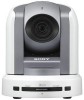
... with builtin pan/tilt/zoom functions
Overview
Long-distance image transmission and pan/tilt/zoom control
• Combined use of the BRBK-303 Optical Multiplex Card, CCFC-M100 Optical Fiber Cable and BRU300/300P Optical Multiplex Unit, and Sony's unique camera connection technology and optical digital multiplex transmission technology allows short to long distance (up to 500 m, or 1,640 feet...
Operating Instructions - Page 16

... POWER button while holding down the RESET button on the RMBR300 Remote Control Unit. You can assign the camera address "1" to "7" manually by setting these selectors as follows:
Camera address Switch 1 Switch 2 Switch 3 0 1 2 3 4 5 6 7
OFF ON
OFF ON ON
OFF ON ON
OFF ON ON ON ON
OFF OFF ON
OFF OFF ON
Q Ceiling bracket mounting screw holes When you install...
Operating Instructions - Page 17
... simultaneously with the same Remote Commander. When you install the cameras close to each other, set different camera numbers. For the camera number setting, see "Operating Multiple Cameras with the Remote Commander" on page 32. B FOCUS buttons Used for focus adjustment. Press the AUTO button to adjust the focus automatically. To adjust the focus manually, press the MANUAL button, and adjust...
Operating Instructions - Page 18

... explosion, use R6 (size AA) manganese or alkaline batteries.
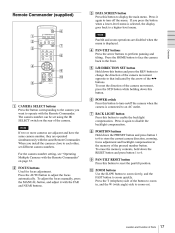
RM-BR300 Remote Control Unit (not supplied)
This manual explains the operations of the RM-BR300 Remote Control Unit when it is used with BRC-300/ 300P cameras. For operations with other cameras, refer to the Operating Instructions supplied with the RM-BR300. Front
890qaqsqd 1 2 3 4 5 6 7
VALUE LOCK PANEL LIGHT...
Operating Instructions - Page 22

... camera. Normally set to "0". With this setting, addresses are assigned to the cameras automatically in the connected order by pressing the POWER button while holding down the RESET button on the RMBR300 Remote Control Unit. You can assign the camera address "1" to "7" manually by setting these selectors as follows:
Camera address 0 1 2 3 4 5 6 7
Overview
BRBK-301 Analog RGB Component Card (not...
Operating Instructions - Page 29

... output from the installed interface card.
Adjusting and Setting With Menus
IR-RECEIVE (infrared signal reception) WIDE (wide mode)
ON: 16:9 aspect ratio of the image of the camera OFF: 4:3 aspect ratio of the image of the camera When it is set to OFF, the camera does not receive the signal from the supplied Remote Commander. Be sure...
Operating Instructions - Page 30

... monitor screen. If you want to display the message each time the camera is operated, set DISPLAY INFO to ON. Set it to OFF to cancel the display.
ANALOG OUT Menu
The ANALOF OUT menu appears only when the BRBK-301 Anaolog RGB Component card is installed in the card slot of the camera.
>OUTPUT 1 SYNC OUTPUT 2
RGB G VBS
Adjusting...
Operating Instructions - Page 31

...
C AM ER A C 2 U FO C R S 1 N SE EA 3
T
AU
REV
N R EV
SIT
Turning on the Power
TO SC RE E
FA
DA TA
3
STD
2
HO M E
6 5
IO N R
1
ST
ES
D
ET
2
O
M
W
L/R DIRECTION SET
Operation Using the Supplied Remote Commander
1
POWER lights. to AC outlet
Press the POWER switch. The camera will turn on and perform the pan/tilt reset action automatically. Press the...
Operating Instructions - Page 35

... the camera address selectors on the bottom of each camera are set to "0." For setting the camera address selectors, see page 16.
3
Note
Be sure to turn on the power of the camera before the power of the Remote Control Unit. Otherwise, the Remote Control Unit cannot recognize the connected camera.
2
Turn on the power of all the connected cameras and the RM-BR300 Remote Control Unit.
Turning...
Operating Instructions - Page 42

... card.
Installation
Attaching an Interface Card
Attach an interface card (not supplied) to the card slot on the rear of the camera.
1
Loosen the two screws to remove the card slot cover.
To remove the interface card
Loosen the two screws on the interface card and pull the card out straight and slowly.
Installing the Camera
To install the camera on a desk
Place the camera...
Operating Instructions - Page 43

...the screw hole used for attaching a tripod on the bottom of the camera. The tripod must be set up on a flat surface and tightened firmly by hand. Use a ...P0.75 Screw tapping used to attach the camera Camera side
Installation and Connections
Before installation
After deciding the shooting direction, make the required holes for the junction box and connecting cables on the ceiling.
Note
φ 46...
Operating Instructions - Page 44

Installation
4
1 2
Set IMG-FLIP to ON in the SYSTEM menu. Loosen the four screws on the bottom of the camera to remove the four feet.
Attach the ceiling bracket (B) to the junction box on the ceiling. Align the holes in the bracket with those in ...
Operating Instructions - Page 45

...into the spaces prepared in the ceiling bracket (B), and temporarily attach them by turning the ceiling bracket (A) with the camera clockwise.
Ceiling
Ceiling bracket (B)
+M3 x 8 (supplied)
4
Attach the wire rope at the same time.... tighten each one in turn.
Note
Installation and Connections
+M3 x 8 (supplied)
For attaching the camera to the ceiling brackets, use only the supplied screws. ...
Operating Instructions - Page 46

... proper steps to ensure that the load of the cables connected does not cause problems.
AC power adaptor MPA-AC1 (supplied) to AC outlet
To remove the camera
DC IN 12V AC power cord (supplied)
1 2
Installation and Connections
Remove the three screws used to attach the camera in step 7 of "Installation." Turn the camera with the bracket counterclockwise to...
Operating Instructions - Page 47

...
Installation and Connections
RM-BR300 Remote Control Unit DC IN 12V AC power cord* VISCA RS-422 cable to AC outlet AC power adaptor* VISCA RS-422 * supplied with the RM-BR300
Note
RM-BR300 Remote Control Unit
to AC outlet
When using the VISCA RS-232C connectors, check that the BOTTOM switch on the bottom of the camera...
Operating Instructions - Page 48

... VISCA RS-232C OUT
to AC outlet
EXT SYNC IN
VIDEO
S VIDEO
IN VISCA RS-232C OUT
to AC outlet
t VIDEO S VIDEO
75-ohm coaxial cable
S-video connecting cable
to composite video input
to S-video input
Installation and Connections
Video monitor, VTR, etc.
Video monitor, VTR, etc.
48
Connections
Operating Instructions - Page 49

... on the bottom of the Remote Control Unit (page 20) are set to RS-232C.
RM-BR300 Remote Control Unit
Connecting a Device Equipped with VISCA RS-422 Connector
Connection via the VISCA RS-422 connectors enables control of multiple cameras. This allows the connection up to 1,200 m (3,937 feet) away. Prepare the connecting cable using the RS-422 connector...
Operating Instructions - Page 50

...Remote Control Unit
VISCA RS-422
to AC outlet
When you install an optional BRBK-301 Analog RGB Component Card into the camera, you can output the signal from the camera by converting it into component video, RGB, composite video or S-video signal.
VISCA RS-422 cable...RS-422
RGB/SYNC
BRBK-301 Analog RGB Component Card
VISCA RS-422 cable CCXC-9DD/9DB cable with D-sub 9-pin plugs (not supplied)
...