Canon LV-7215 driver and firmware

Related Canon LV-7215 Manual Pages
Download the free PDF manual for Canon LV-7215 and other Canon manuals at ManualOwl.com
lv7210_series_basic_cmd.pdf - Page 10

... Serial Functional Specification for LV-5210/7215/7210
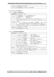
6.8 Computer 1 COMMAND
COMMAND "C05" [CR]
Detail
Select Computer 1 input. When optional accessory, MCI BOX is installed, select the function
(Memory Card / Wireless / Wired).
Response
Acceptable [ACK] [CR] Unacceptable "?" [CR]
6.9 Computer 2 COMMAND
COMMAND "C06" [CR]
Detail
Select Computer 2 input. When Computer 2 terminal is set...
lv7210_series_basic_cmd.pdf - Page 22

...
ON)
"00" [CR] = Vertical and right-and left (four directions)
reversal setting (status: Ceiling ON)
Unacceptable "?" [CR]
7.7 Temp Read COMMAND
COMMAND "CR6" [CR]
Detail
Get the temperature inside a projector. When some temperature sensors are installed in the projector, it is possible to know the temperature all at once.
Response
Acceptable
"%1_%2_...
lv7210_series_exp_cmd.pdf - Page 7

...9600 / 19200 8 bit
Parity
N/A
Stop Bit
1
Flow Control
N/A
Note1) transfer rate: initial setting value is 19200 Note2) transfer rate can be changed by service MODE
2.2 Connection
Must use a dedicated serial cable that come with the projector for a connection to a
COMPUTER and a projector.
PC
Projector
COM No.1
Control Port
CD 1
1
RXD 2
2
TXD 3
3
DTR 4
4
SG 5
5
DSR 6
6
RTS...
lv7210_series_exp_cmd.pdf - Page 23
... it is in the usual Power ON status.) The Command works as the same as the remote controls's unit "INPUT" button. Note1:) If trying to select Input-2 TERMINAL when setting
Input-2(COMPUTER)to MONITOR Out, the projector returns "101". Note2:)The selection of Input-1 is not COMPUTER-1 but Memory card/ Wireless/Network when Option box is installed to Input-1 (COMPUTER1).
Response
Acceptable...
lv7210_series_exp_cmd.pdf - Page 47

...COMMAD FUNCTIONAL SPECIFICATION for LV-5210/7215/7210
9.12.4 ....6 CR_TEMPFAILCOMMAND
COMMAND "CR_TEMPFAIL" [CR]
Details
Get the temperature inside a projector. When some temperature sensors are installed in the projector, it is possible to know the temperature all at once.
Acceptable "...projector is reset, " 00.0S"is set.
In short, previous data is deleted.
Unacceptable "?" [CR]
...
lv7215_7210_5210_manual.pdf - Page 2

...
Compliance
Connecting the AC Power Cord
Features and Design
Part Names and Functions
Front Back Bottom Terminal Top Remote Control Unit Laser Pointer Function Pointer Function Remote Control Code Wireless Mouse Operation Remote Control Operating Range Remote Control Batteries Installation
Installation
Positioning the Projector Adjustable Feet Connecting to a Computer Connecting to Video Equipment...
lv7215_7210_5210_manual.pdf - Page 3

... maintained. Do not cover the ventilation slot on the projector. Heat buildup can reduce the service life of your projector, and can also be dangerous.
SIDE and TOP
REAR
- The remote control, supplied to this projector, emits the laser beam as the Laser pointer function from laser light window while pressing the LASER button (for 1 minute / Signal...
lv7215_7210_5210_manual.pdf - Page 4

... projector from wall outlet and refer servicing to qualified service personnel under the following conditions: a. When the power cord or plug is damaged or frayed. b. If liquid has been spilled into the projector. c. If the projector has been exposed to rain or water. d. If the projector does not operate normally by following the
operating instructions. Adjust only those controls...
lv7215_7210_5210_manual.pdf - Page 5

Safety Instructions
Installing the Projector in Proper Position
Install the projector properly. Improper installation may reduce the lamp life and cause a fire hazard.
20˚ Do not tilt the projector more than 20 degrees above and below.
20˚
Do not put the projector on either side to project an image.
Do not point the projector down to project an...
lv7215_7210_5210_manual.pdf - Page 6

Compliance
Federal Communication Commission Notice
Multimedia Projector, Model : LV-7215, LV-7210, LV-5210 This device complies with Part 15 of the FCC Rules. Operation is subject to the following two conditions:
(1) This device may not cause harmful interference, and (2) this device must accept any interference received, including interference that may cause undesired operation. Note : This ...
lv7215_7210_5210_manual.pdf - Page 12

... the laser beam is being emitted from the Laser Light Window or a signal is being sent from the remote control to the projector.
e KEYSTONE button
Corrects keystone distortion. (p20, 38)
r AUTO PC button
Operates the Auto PC adjustment function. (p26)
t COMPUTER button
Selects input source (COMPUTER 1 or COMPUTER 2). (p24)
y POINT (UP/DOWN/LEFT/RIGHT) button
Selects an...
lv7215_7210_5210_manual.pdf - Page 13

... put on the remote control.
Laser Light Window
Pointer Function
You can move Spotlight or Pointer of the projector with the remote control unit to emphasize ... clear the Spotlight or Pointer displayed on the screen, press the LASER button toward the projector and see if the LASER...the pattern of Pointer (Arrow, Finger, and Dot) in the Setting Menu. See "Pointer" on page 40.
After the Laser pointer...
lv7215_7210_5210_manual.pdf - Page 15

Part Names and Functions
Remote Control Operating Range
Point the remote control unit toward the projector (Infrared Remote Receiver) whenever pressing any button. Maximum operating range for the remote control is about 16.4' (5m) and 60° in front of the projector.
16.4' (5 m)
60°
Remote Control Batteries Installation
1 Remove the battery compartment lid.
Press the lid downward and ...
lv7215_7210_5210_manual.pdf - Page 16

Installation
Positioning the Projector
This projector is designed to project on a flat projection surface and can be focused from 3.3'(1.0m) - 25.3'(7.7m). Refer to the figure and the table below for the screen size and the distance between the projector...)
CAUTION
Tilt the projector within the adjustable range in order to preserve the life of the lamp. The proper angle should be set. See page 5....
lv7215_7210_5210_manual.pdf - Page 17

...USB
COMPUTER
AUDIO IN
DVI-I / RGB IN-1
DVI-I/ RGB IN-1
AUDIO R IN L
VIDEO IN
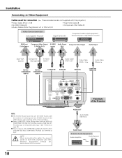
NOTE
G This terminal is switchable. Set the terminal up as either Computer input or Monitor output before using this terminal. (See Page 39.)
SERVICE PORT S-VIDEO IN COMPUTER AUDIO IN
RESET
MCI
RGB IN-2/
COMPONENT IN/
RGB OUT
AUDIO OUT
Terminals of the Projector
NOTE : When connecting the cable, the power...
lv7215_7210_5210_manual.pdf - Page 18
... Cable ✽
Audio Cable (RCA x 2) ✽
Video Cable (RCA x 1s) ✽
Audio Cable (Stereo) ✽
RGB IN-2 / COMPONENT IN/
RGB OUT
RGB IN-2 / COMPONENT IN/
RGB OUT
S-VIDEO IN
AUDIO IN
VIDEO IN
DVI-I/ RGB IN-1
AUDIO R IN L
VIDEO IN
COMPUTER AUDIO IN
SERVICE PORT S-VIDEO IN COMPUTER AUDIO IN
RESET
MCI
RGB IN-2/
COMPONENT IN/
RGB OUT
AUDIO OUT
Terminals of the Projector...
lv7215_7210_5210_manual.pdf - Page 23

... Bar
For computer source
Guide Window
Shows the selected Menu of the OnScreen Menu.
PC System Menu
Used to select computer system. (p25)
Image Select Menu
Used to select an image level among Standard, High contrast, and Custom. (p29)
Screen Menu
Used to adjust size of image. [Normal / True / Wide / Digital zoom +/-] (p31)
Setting Menu
Used...
lv7215_7210_5210_manual.pdf - Page 26
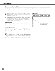
...
Move the red frame pointer to the Auto PC Adj. icon and press the SET button.
NOTE
G The PC Adjust Menu cannot be operated when the input signal is digital, a signal compatible with HDCP, or a memory card is installed into Multi Card Imager.
G The Auto PC Adjust cannot be operated when 480i, 575i, 480p, 575p, 720p...
lv7215_7210_5210_manual.pdf - Page 41
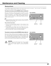
... to normal, the WARNING
indicator still continues to flash. When the projector is turned on again, the WARNING indicator stops flashing.
TOP CONTROL
KEY
STONE OL +
LAMP REPLACE
WARNING
POWER
Then check the items below.
Did you provide appropriate space for the projector to be ventilated? Check the installing condition to see if ventilation slots are not...
lv7215_7210_5210_manual.pdf - Page 50
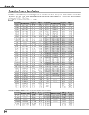
...computers with the V, H-Frequency mentioned below and less than 100/MHz of Dot Clock.
These modes are not available on LV-5210.
ON-SCREEN DISPLAY
RESOLUTION
VGA 1
640 x 480
VGA 2
720 x 400
VGA 3
640 x 400
VGA 4
640 x 480
VGA 5
640 x 480
VGA 6
640 x 480
VGA 7
640 x 480
MAC LC13 640 x 480
MAC...digital from DVI terminal, refer to the chart below.
ON-SCREEN DISPLAY
RESOLUTION
D-VGA ...