Sony XCDV60CR driver and firmware

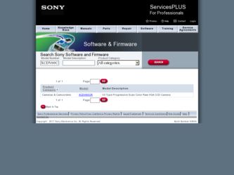
Related Sony XCDV60CR Manual Pages
Download the free PDF manual for Sony XCDV60CR and other Sony manuals at ManualOwl.com
User Manual (XCDV60_V60CR_SX90_SX90CR_U100_U100CR_Operating_Instructions) - Page 1
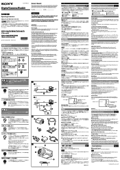
... power and image/control signals are transmitted through this cable. To prevent a poor connection or damage to the camera or cable, use the cable equipped with fixing screws.
C-mount lens (commercially available) Use an appropriate lens for the camera module and usage.
Camera module interface board (commercially available) Install the board in a PCI bus slot of a host device such...
User Manual (XCDV60_V60CR_SX90_SX90CR_U100_U100CR_Operating_Instructions) - Page 2
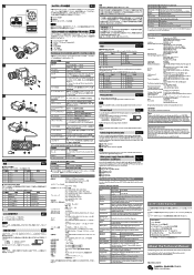
... function Description
3 x 3 Filter
Switching the 3 x 3 filter
Sharpness
Adjusting the image contour strength
These control items comply with Digital Camera Protocol, Ver. 1.31, of the IEEE1394 Standard. For more details, refer to the Technical Manual.
Specifications
Pickup device
Progressive scan IT CCD
XCD-V60CR/V60/SX90CR/SX90: 1/3 type
XCD-U100CR/U100: 1/1.8 type
Interface
IEEE1394b...
User Manual (XCDV60_V60CR_SX90_SX90CR_U100_U100CR_Technical_Manual) - Page 2
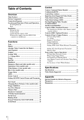
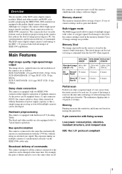
... 12 User Free Memory 12 Memory Shot 13 Broadcast Command 13 1394 Bus Synchronization 13 Partial Scan 14 Binning Mode 15 Format7 Mode4 for XCD-V60/V60CR 15 16-bit Mode 15
Control
Camera Command Status Register 16 ConfigurationROM 17 Control Base Address 19 Inquiring about Supported Video Modes ..........19 Video Mode Settings (S800 20 Video Mode Settings (S400 20 Starting...
User Manual (XCDV60_V60CR_SX90_SX90CR_U100_U100CR_Technical_Manual) - Page 3
... IEEE1394b cable only.
Broadcast delivery of commands
The camera settings for all the cameras connected to the same bus can be changed at the same time. For example, the gain or shutter speed is set to the same value on all
the cameras, or exposure starts on all the cameras simultaneously using a software trigger.
Memory channel
The memory channel allows storage of...
User Manual (XCDV60_V60CR_SX90_SX90CR_U100_U100CR_Technical_Manual) - Page 4
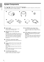
... camera module. The power and image/control signals are transmitted through this cable. To prevent a poor connection or damage to the camera or cable, use the cable equipped with fixing screws.
3 C-mount lens (commercially available) Use an appropriate lens for the camera module and usage.
4 Camera module interface board (commercially available) Install the board in a PCI bus slot of a host device...
User Manual (XCDV60_V60CR_SX90_SX90CR_U100_U100CR_Technical_Manual) - Page 7

... adaptor (not supplied) on the camera module. Use a tripod screw with a protrusion ( ) extending from the installation surface, as follows:
1 IEEE1394b connector
2 Fixing screws
3 IEEE1394b camera cable (not supplied)
Note
Loose fixing screws may cause a poor connection or damage to the camera or cable. Be sure to tighten the fixing screws.
When power supply from the IEEE1394b connector...
User Manual (XCDV60_V60CR_SX90_SX90CR_U100_U100CR_Technical_Manual) - Page 10
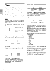
... allows shooting of multiple images with different camera settings using only one trigger signal. The camera settings should be prestored in memory channels.
Trigger
Exposure
Setting in Memory channel 1
Setting in Memory channel 2
Trigger mode 15 (Sequential trigger mode) Trigger mode 15 allows shooting of images by loading the camera settings prestored in memory channels in sequence each time...
User Manual (XCDV60_V60CR_SX90_SX90CR_U100_U100CR_Technical_Manual) - Page 12

....
Setting AE/AWB Control Frame and Parameters
The detection frame for Auto Exposure and Auto White Balance can be set. ...Memory
This camera is equipped with a 256-byte memory space so the user can write and read data freely. The written data is retained after the power is turned off. For example, the user can name the camera and note the installation conditions using this memory space. The memory...
User Manual (XCDV60_V60CR_SX90_SX90CR_U100_U100CR_Technical_Manual) - Page 13
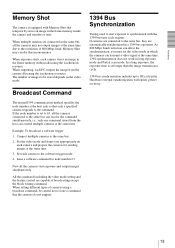
... output images simultaneously.
All the commands including the video mode setting and the feature control are capable of broadcasting except the block writing command. When setting different types of cameras using a broadcast command, be careful not to issue a command that the cameras do not support.
1394 Bus Synchronization
Timing used to start exposure is synchronized with the...
User Manual (XCDV60_V60CR_SX90_SX90CR_U100_U100CR_Technical_Manual) - Page 17
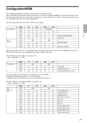
... to identify the device. The serial number and firmware version of the camera are stored in ConfigurationROM to be used when required. Note that the setting method for the serial number and firmware version information is of Sony's unique specification and is not compatible with cameras of other manufacturers.
The following explanation uses XCD-V60CR as an example.
Bus Info Block
Root...
User Manual (XCDV60_V60CR_SX90_SX90CR_U100_U100CR_Technical_Manual) - Page 18

...:
Vendor_unique_info_0 is the firmware version. Vendor_unique_info_1 is the hardware version. Vendor_unique_info_2 is the link version. Vendor_unique_info_3 is the serial number of the camera.
VendorNameLeaf
Vender Name Leaf
Offset 464h 468h 46h 470ch
0-7
8-15
0003
00
00
00
00
53
4F
16-23
24-31
CRC
00
00
00
00
4E
59
" SONY "
For offset address 464h, the length...
User Manual (XCDV60_V60CR_SX90_SX90CR_U100_U100CR_Technical_Manual) - Page 20
...
40000000h A0000000h
40000000h 40000000h
00008003h 00008003h
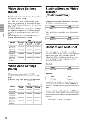
Video Mode Settings (S400)
When the camera is used under1394A (S400) conditions, set the isochronous transfer speed to 400 Mbps. In this case, set the frame rate to 15 fps, as this mode does not support data transfer of SXGA 30 fps.
Address
F0F00600h (FrameRate)
F0F00604h (VideoMode)
F0F00608h (VideoFormat)
F0F0060Ch...
User Manual (XCDV60_V60CR_SX90_SX90CR_U100_U100CR_Technical_Manual) - Page 22
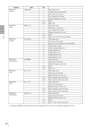
...control possible. The value can be read out. Auto setting can be selected. Manual setting can be selected. Min. 3 Max. 1150 This feature exists. The value can be read out. Auto setting can be selected. Manual setting... Software Trigger Mode exists. Trigger Mode0 exists. Trigger Mode1 exists. Trigger Mode14 exists. Trigger Mode15 exists. This feature exists. The value can be read out. Manual setting ...
User Manual (XCDV60_V60CR_SX90_SX90CR_U100_U100CR_Technical_Manual) - Page 23
...
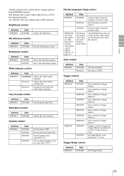
Set Gain manually. Set Gain to AUTO.
Trigger control
Address
Data
F0F00830 82000000
82010000
820E000d
820F000d
82E00000
82E10000
82EE000d
82EF000d
F0F0062C 80000000
00000000
Sets to Hardware Trigger Mode0.
Sets to Hardware Trigger Mode1.
Sets to Hardware Trigger Mode14.
Sets to Hardware Trigger Mode15.
Sets to Software Trigger Mode0.
Sets to Software Trigger Mode1.
Sets to Software...
User Manual (XCDV60_V60CR_SX90_SX90CR_U100_U100CR_Technical_Manual) - Page 32

... table
1/100,000 to 16 s (Absolute value control possible)
Auto/Manual (Black and white model: 0 to 24 dB / Color model: 0 to 18 dB)
Edge detection (Mode0), Exposure time setting by trigger width (Mode1), Software trigger (IEEE1394 bus), Bulk trigger, Sequential trigger, Trigger inhibition setting, Trigger/strobe delay setting
+8 to +30 V (from IEEE1394b cable or 12-pin connector)
2.8 W (12...
Product Brochure (xcd_series) - Page 2

... 1394b ports allowing multiple cameras to be daisy-chained and controlled from a single PC. A daisy-chain configuration with a large number of cameras*1 is made possible by their EIAJ 12-pin connector, which allows external power to be supplied to the cameras.
*1 Up to 62 cameras, with additional external power being supplied, can be daisy-chained.
IEEE 1394b 9-pin cable...
Product Brochure (xcd_series) - Page 3
... greater sensitivity, faster capture speeds, and quicker processing.
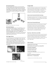
New Sony 1394.b Driver and SDK
A new low level 1394.b driver for these cameras achieves reliable and efficient image transfer without relying on Microsoft's standard Windows® driver. In addition, the new cameras are backward compatible with the current fcam 1394a driver.
Other Features
Hardware LUT (Look Up Table) Built...
Product Brochure (xcd_series) - Page 4

... exposure duration (Mode 1), Programmable trigger (via the IEEE1394 bus), Trigger inhibit setting, Trigger/Strobe delay setting, Single/Bulk trigger mode
Image memory
16 MB
Memory channel
15 channels for parameter settings
Broadcast delivery
Camera setting, Software trigger via IEEE1394 bus
Readout features
Partial Scanning,
Partial Scanning, LUT,
Binning, LUT, 3x3 filter Bayer Pattern...