Sony HDWS280 driver and firmware


Related Sony HDWS280 Manual Pages
Download the free PDF manual for Sony HDWS280 and other Sony manuals at ManualOwl.com
Product Manual (Operation Manual 1st Edition (Revised 5)) - Page 2

...only with dry cloth. • Do not block any ventilation openings. Install in accordance
with the manufacturer's instructions. • Do not install near any heat sources such as radiators, heat
registers, stoves, or ... time. • Refer all servicing to qualified service personnel. Servicing is required when the apparatus has been damaged in any way, such as power-supply cord or plug is damaged...
Product Manual (Operation Manual 1st Edition (Revised 5)) - Page 3
... outdoors), E4 (controlled EMC environment, ex. TV studio)
The manufacturer of this product is Sony Corporation, 1-7-1 Konan, Minato-ku, Tokyo, Japan. The Authorized Representative for EMC and product safety is Sony Deutschland GmbH, Hedelfinger Strasse 61, 70327 Stuttgart, Germany. For any service or guarantee matters please refer to the addresses given in separate service or guarantee documents...
Product Manual (Operation Manual 1st Edition (Revised 5)) - Page 6

...System Configurations 11 1-3 Using the CD-ROM Manual 12
1-3-1 Preparations 12
1-3-2 Reading the CD-ROM Manual 12
Chapter 2 Names and Functions of Parts
2-1 Front Panel 13 2-1-1 Menu Operation Section 14 2-1-2 Tape Transport Section 15 2-1-3 Display Window 16
2-2 Rear Panel 20
Chapter 3 Preparations
3-1 Preparing Power Sources 22
3-1-1 Supplying Power 22
3-1-2 Using the Battery Pack...
Product Manual (Operation Manual 1st Edition (Revised 5)) - Page 12

... the operation manual.
Memo
The files may not be displayed properly, depending on the version of Adobe Reader. In such a case, install the latest version you can download from the URL mentioned in "13-1 Preparations" above.
Note
If you have lost or damaged the CD-ROM, you can purchase a new one to replace it. Contact your Sony service representative.
12...
Product Manual (Operation Manual 1st Edition (Revised 5)) - Page 14

...PAGE/HOME button 6 SHIFT button
8 MULTI CONTROL knob
a Function buttons Select and set menu items displayed in the display window.
b Display window Displays menus, audio level meters, and data such as time data or meta-data. The DISPLAY button let you switch to the video monitor display.
For details, see "2-1-3 Display Window" on page 16.
c MENU button Displays a setup menu item in the time data...
Product Manual (Operation Manual 1st Edition (Revised 5)) - Page 16
... 2 MONI R : 2 D-STOP
DOLBY NR P ROLL
59.94i SDI ASMBL CONFI ON RECORDER
OFF LTC DF VITC LTC EXT-LTC R-RUN REM:00M
TCG SET HOME
00:00:00:00.
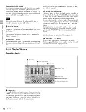
4 Condition area
5 Format area 6 Timecode setup area 7 Time data display area
a Menu area Normally displays the function menu. When you press the MENU button, the functions...
Product Manual (Operation Manual 1st Edition (Revised 5)) - Page 19

... press the DISPLAY button, the display window changes to the video monitor display.
A Audio level meter LEVEL MT on the P3 AUDIO page of the function menu decides whether the meter is to be displayed and on which side, left or right, it is displayed in the display window.
B Up-converter, down-converter display If setup menu item 140 is set to ON...
Product Manual (Operation Manual 1st Edition (Revised 5)) - Page 22

... on the rear panel is set to ON, AC power is supplied.
Battery power supply
The BP-GL95 lithium-ion battery pack provides up to 80 minutes of continuous recording time, and the BP-L80S provides up to 55 minutes.
For details on charging battery packs, refer to the operation manual for the battery charger...
Product Manual (Operation Manual 1st Edition (Revised 5)) - Page 23
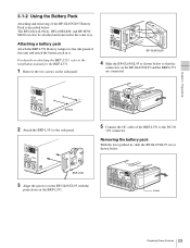
... this unit and attach the battery pack in it.
For details on attaching the BKP-L551, refer to the installation manual for the BKP-L551.
1 Remove the two screws on the side panel.
BP-GL65/GL95
4 Slide the...the BKP-L551 are connected.
Screws
2 Attach the BKP-L551 to the side panel.
5 Connect the DC cable of the BKP-L551 to the DC IN
12V connector.
Removing the battery pack
With the lever pushed in,...
Product Manual (Operation Manual 1st Edition (Revised 5)) - Page 26

... when you wish to record on the cassette again.
Cassette
1 Supply the power. 2 Load a cassette in the direction shown in the figure
above after checking the following points.
• That ERROR-10 is not displayed in the display window.
• That there is no slack in the tape.
If ERROR-10 appears in the display window This means that there...
Product Manual (Operation Manual 1st Edition (Revised 5)) - Page 32

.... MENU: Change the settings of the internal digital video processor, using the setup menu.
Note When controlling the unit with the HKDV-900, set to MENU.
VIDEO
Sets the HD/SD video signal output level (−∞ to +3 dB). PRESET: Regardless of manually set values,
the video signal is set to the standard level. Manual setting: With the displayed setting flashing, you can adjust the...
Product Manual (Operation Manual 1st Edition (Revised 5)) - Page 38

... "Memory Stick" application software may be modified or changed by Sony without prior notice.
3-9-1 Notes on "Memory Stick"
What is "Memory Stick"?
"Memory Stick" is a new compact, portable and versatile IC (Integrated Circuit) recording medium with a data capacity that exceeds that of a floppy disk. "Memory Stick" is specially designed for exchanging and sharing digital data among "Memory Stick...
Product Manual (Operation Manual 1st Edition (Revised 5)) - Page 42

... previous contents repeatedly.
When REPL (Manual Cassette Replace) is selected When recording ends, the tape stops at the end or is rewound to the beginning and stops according to the setting of setup menu item 125 "AUTO REWIND." When the tape stops, the cassette mark in the display window begins flashing. To continue recording, insert a new cassette into...
Product Manual (Operation Manual 1st Edition (Revised 5)) - Page 47

... REM:00M
TCG SET HOME
00:00:00:00.
DISPLAY MULTI CONTROL REMOTE
MENU RESET
PREROLL
PUSH PITCH CTL JOG/SHUTTLE
REW
PLAY F FWD STOP
REC PAUSE
STANDBY
PAGE button
MULTI CONTROL knob
1 Press the PAGE button to display the P5 EDIT page in
the menu display area.
2 Press the R/P function button to set a VTR (PLAYER
or RECORDER) for modifying...
Product Manual (Operation Manual 1st Edition (Revised 5)) - Page 53

...set it to ON.
D-STOP appears in the condition area of the display window, and you can detect the stop code.
If three or more stop codes are detected during playback, the tape stops, and D-STOP flashes...ROLL
ASSEMBLE 59.94i SDI ASMBL CONFI ON RECORDER
OFF LTC DF VITC LTC EXT-LTC R-RUN REM:00M
TCG SET HOME
00:00:00:00.
DISPLAY MULTI CONTROL REMOTE
MENU RESET
PREROLL
PUSH PITCH CTL JOG/SHUTTLE
...
Product Manual (Operation Manual 1st Edition (Revised 5)) - Page 58
... when you choose to output UMIDs. Make these settings using setup menu item 651.
For details on setup menu item 651, see page 72.
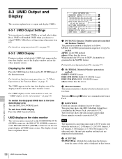
8-3-2 UMID Display
During recording and playback, UMID data appear in the time data display area of the display window and on the video monitor screen.
Displaying the UMID
Press the UMID function button on the...
Product Manual (Operation Manual 1st Edition (Revised 5)) - Page 62

... to select the
displayed setup menu item 013.
4 Turn the MULTI CONTROL knob or press the - or +
function button to display PUSH SET.
5 Press the SET function button.
6 Turn the MULTI CONTROL knob or press the - or +
function button to select the system frequency.
7 Press the SET function button.
TURN OFF/ON POWER!! appears.
8 Turn the power OFF.
When the...
Product Manual (Operation Manual 1st Edition (Revised 5)) - Page 67

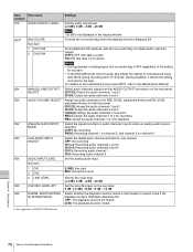
...]: Rewind the tape automatically.
130
TIMER DISPLAY DIMMER Set the brightness of the display window.
CONTROL
100% [75%] 50% OFF
137
TRACKING CONTROL VIA Select whether the search dial is enabled for tracking control.
JOG/SHUTTLE DIAL
[OFF]: Disabled the tracking control
ON: Enabled the tracking control during playback
138
STOP CODE FUNCTION Set for detection of the stop code...
Product Manual (Operation Manual 1st Edition (Revised 5)) - Page 70
... in the display window, and press the SET function button. The ID code setting mode is obtained. Select the digit to be set by pressing the T or t function button. When you select all digits, set the SET function button again. The ID code is stored and the ID code setting mode is terminated.
Select whether or not to record the ID...
Product Manual (Operation Manual 1st Edition (Revised 5)) - Page 76
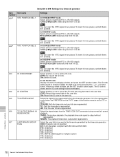
... 3 LINE LEVEL CUE REC LEVEL ATT DIGITAL AUDIO MUTING IN FF/REW MODE
Settings
Set the audio output level. [+4 dB] 0 dB -3 dB -20 dB
Note −20 dB is not displayed in the display window.
Controls the non-audio flag when the playback format is Betacam SX.
During Betacam SX playback, sets the non-audio flag of a digital audio output as follows. [OFF]: OFF...