MSI P6NGM-FD - Motherboard - Micro ATX driver and firmware
Drivers and firmware downloads for this MSI item

Related MSI P6NGM-FD Manual Pages
Download the free PDF manual for MSI P6NGM-FD and other MSI manuals at ManualOwl.com
Getting Started Guide - Page 5
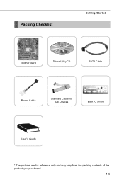
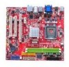
Packing Checklist
Getting Started
Motherboard
Driver/Utility CD
SATA Cable
Power Cable
Standard Cable for IDE Devices
Back IO Shield
User's Guide
* The pictures are for reference only and may vary from the packing contents of the product you purchased.
1-5
Getting Started Guide - Page 6
Chapter 2
Hardware Setup
This chapter tells you how to install the CPU, memory modules, and expansion cards, as well as how to setup the jumpers on the mainboard. Also, it provides the instructions on connecting the peripheral devices, such as the mouse, keyboard, etc. W hile doing the installation, be careful in holding the components and follow the installation procedures.
Getting Started Guide - Page 8
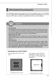
... heat dissipation. Replaceing the CPU While replacing the CPU, always turn off the ATX power supply or unplug the power supply's power cord from the grounded outlet first to ensure the safety of CPU. Overclocking This mainboard is designed to support overclocking. However, please make sure your components are able to tolerate such abnormal setting, while doing overclocking. Any...
Getting Started Guide - Page 9
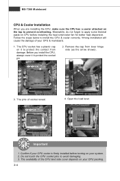
... to protect the contact from damage. Before you install the CPU, always cover it to protect the socket pin.
2. Remove the cap from lever hinge side (as the arrow shows).
3. The pins of socket reveal.
4. Open the load lever.
Important
1. Confirm if your CPU cooler is firmly installed before turning on your system. 2. Do not...
Getting Started Guide - Page 11
MS-7366 Mainboard
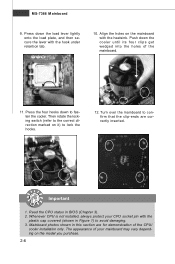
9. Press down the load lever lightly onto the load plate, and then secure the lever with the hook under ...mainboard to confirm that the clip-ends are correctly inserted.
locking switch
Important
1. Read the CPU status in BIOS (Chapter 3). 2. Whenever CPU is not installed, always protect your CPU socket pin with the
plastic cap covered (shown in Figure 1) to avoid damaging. 3. ...
Getting Started Guide - Page 12
Hardware Setup
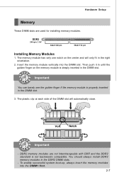
Memory
These DIMM slots are used for installing memory modules.
DDR2
240-pin, 1.8V
64x2=128 pin
56x2=112 pin
Installing Memory Modules
1. The memory module has only one notch on the center and will only fit in the right orientation.
2. Insert the memory module vertically into the DIMM slot. Then push it in until the golden...
Getting Started Guide - Page 16
Hardware Setup
Connectors
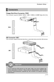
Floppy Disk Drive Connector: FDD1
This connector supports 360KB, 720KB, 1.2MB, 1.44MB or 2.88MB floppy disk drive.
FDD1
IDE Connector: IDE1
This connector supports IDE hard disk drives, optical disk drives and other IDE devices.
IDE1
Important
If you install two IDE devices on the same cable, you must configure the drives separately to Primary / Slave mode by setting ...
Getting Started Guide - Page 24
...Setup
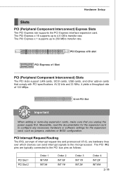
Slots
PCI (Peripheral Component Interconnect) Express Slots
The PCI Express slot supports the PCI Express interface expansion card. The PCI Express x 16 supports up to 4.0 GB/s transfer rate. The PCI Express x 1 supports up to 250 MB/s transfer rate.
PCI Express x16 slot
PCI Express x1 Slot
PCI (Peripheral Component Interconnect) Slots
The PCI slots support LAN cards, SCSI cards, USB cards...
Getting Started Guide - Page 27
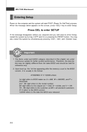
... 1st line appearing after the memory count is the BIOS version. It is usually in the format: A7366NMS V1.0 122506 where: 1st digit refers to BIOS maker as A = AMI, W = AWARD, and P = PHOENIX. 2nd - 5th digit refers to the model number. 6th digit refers to the chipset as I = Intel, N = nVidia, and V = VIA. 7th - 8th digit refers to the customer as...
Getting Started Guide - Page 33
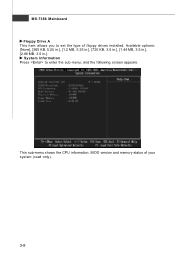
... Floppy Drive A This item allows you to set the type of floppy drives installed. Available options: [None], [360 KB, 5.25 in.], [1.2 MB, 5.25 in.], [720 KB, 3.5 in.], [1.44 MB, 3.5 in.], [2.88 MB, 3.5 in.]. System Information Press to enter the sub-menu, and the following screen appears.
This sub-menu shows the CPU information, BIOS version and memory status...
Getting Started Guide - Page 43
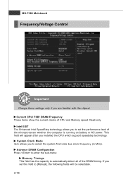
... CPU and Memory speed. Read-only. Intel EIST The Enhanced Intel SpeedStep technology allows you to set the performance level of the microprocessor whether the computer is running on battery or AC power. This field will appear after you installed the CPU which support speedstep technology. System Clock Mode item allows you to select the system front side bus...
Getting Started Guide - Page 44
BIOS Setup
tCL (CAS Latency) W hen the Memory Timings sets to [Manual], the field is adjustable.This controls the CAS latency, which determines the timing delay (in clock cycles) before SDRAM starts a read command after receiving it.
tRCD W hen DRAM is refreshed, both rows and columns are addressed separately. This setup item allows you to determine the timing of...