Lantronix SISTP1040-551-LRT driver and firmware
Drivers and firmware downloads for this Lantronix item

Related Lantronix SISTP1040-551-LRT Manual Pages
Download the free PDF manual for Lantronix SISTP1040-551-LRT and other Lantronix manuals at ManualOwl.com
SISTP1040-551-LRT Install Guide Rev B - Page 2

Lantronix
SISTP1040-551-LRT Install Guide
Intellectual Property
© 2022 Lantronix, Inc. All rights reserved. No part of the contents of this publication may be transmitted or reproduced in any form or by any means without the written permission of Lantronix. Lantronix is a registered trademark of Lantronix, Inc. in the United States and other countries. All other trademarks and trade names...
SISTP1040-551-LRT Install Guide Rev B - Page 3

Lantronix
SISTP1040-551-LRT Install Guide
Table of Contents
1 Introduction ...4 Product Description ...4 Ordering Information...4 About This Manual...4 Related Manuals...4 Features ...4 PoE Features ...5 Specifications ...5 Application Example ...6
2 Installation ...7 Package Checklist ...7 Cautions and Warnings ...7 Safety Instructions ...7 Dimensions ...8 Front, Top, and Back Panels ...9 DIN-...
SISTP1040-551-LRT Install Guide Rev B - Page 4

... • Troubleshoot switch installation
Related Manuals
• SISTP1040-551-LRT Quick Start Guide, 33840 • PS-DC-DUAL-5624T Power Supply Install Guide, 33788
Features
• IEEE 802.3af/at/bt PoE and PoH PSE support • Redundant Power Input terminals; Reverse power protection • IP30 Ingress protection • Full Gigabit Ethernet ports • SFP support for 100/1000Base...
SISTP1040-551-LRT Install Guide Rev B - Page 5
Lantronix
SISTP1040-551-LRT Install Guide
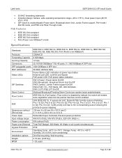
• 2k MAC forwarding addresses • Industrial design: fanless, wide operating temperature range (-40 to +75°C), Dual power input (48~57
VDC), IP30 • DIP switch to enable/disable Power alarm, Broadcast storm limit, Jumbo Frame support, PoH mode /
802.3bt mode, and PSE Link Pass Through mode
PoE Features
• IEEE 802.3bt compliant...
SISTP1040-551-LRT Install Guide Rev B - Page 6

Lantronix
SISTP1040-551-LRT Install Guide
Warranty
5 Years
Application Example
The switch is ideal for applications such as PoE Lighting, IP camera with heater, digital signage, and situations involving PDs that require higher power PoE.
33841 Rev. B
https://www.lantronix.com/
Page 6 of 26
SISTP1040-551-LRT Install Guide Rev B - Page 7

Lantronix
SISTP1040-551-LRT Install Guide
2 Installation
Package Checklist
Verify that the box contains these items:
One SISTP1040-551-LRT switch Two Wall-mount brackets One DIN-Rail Clip Four M4 Screws (for Wall mount brackets and DIN Clip) One DC power Terminal Block One printed Quick Start Guide One documentation postcard
Contact your sales representative if any item is missing. Please save...
SISTP1040-551-LRT Install Guide Rev B - Page 9

Lantronix
SISTP1040-551-LRT Install Guide
Front, Top, and Back Panels
The front panel provides the LEDs and Ethernet interface connections (RJ45, Fiber/SFP). The top panel contains the Power and Alarm connections, Ground screw, and DIP switch. The back panel contains holes for DIN-Rail and Wall Mounting.
Front Panel
Top Panel 1
Back Panel
...
SISTP1040-551-LRT Install Guide Rev B - Page 10

Lantronix
SISTP1040-551-LRT Install Guide
DIN-Rail Mounting
1. Screw the DIN-Rail bracket onto the switch with the provided bracket and screws. 2. Hook the unit over the DIN rail. 3. Push ... onto the switch with the M4 screws provided. 3. Screw the switch and wall mount plate onto the wall (screws not provided).
33841 Rev. B
https://www.lantronix.com/
Page 10 of 26
SISTP1040-551-LRT Install Guide Rev B - Page 11

Lantronix
SISTP1040-551-LRT Install Guide
Ground Connection
The switch must be properly grounded for optimum system performance. Use 18 AWG minimum, green and yellow wires.
Ethernet Interface Connection (RJ45 Ethernet)
The switch provides two types of interfaces: electrical (RJ45) and optical (SFP). To connect the Ethernet interface via RJ45:
1. Connect to a PC using a straight-through or a ...
SISTP1040-551-LRT Install Guide Rev B - Page 12

Lantronix
SISTP1040-551-LRT Install Guide
Ethernet Interface Connection (Fiber, SFP)
100/1000 Mbps fiber port: Insert an MSA compliant 100 Mbps or 1000 Mbps small form pluggable transceiver (SFP) in the SFP slot.
For each fiber port there is a transmit (TX) and receive (RX) signal. Make sure that the transmit (TX) port of the switch connects to the receive (RX...
SISTP1040-551-LRT Install Guide Rev B - Page 13

Lantronix
SISTP1040-551-LRT Install Guide
DIP Switch Settings
The top panel 5-position DIP switch is labeled SW and is located directly below the terminal block connector. The default setting for all is Off .
DIP # 1 2 3 4
5
State On Off On Off On Off On Off
On
Off
Description Enable the Power alarm. Disable the Power alarm. Enable Broadcast Storm rate limit. Disable...
SISTP1040-551-LRT Install Guide Rev B - Page 14

Lantronix
SISTP1040-551-LRT Install Guide
4. PoE PoH / PoE 802.3bt Mode
PoH (Power over HDBaseT): HDBaseT is a global standard for distribution of ultra-high-definition video & audio, Ethernet, controls, USB and up to 100W of power over a single cable, for up to 100 meters (328 feet).
For PoH information see https://hdbaset.org/. In PoH mode the switch becomes compatible with PDs supporting PoH...
SISTP1040-551-LRT Install Guide Rev B - Page 15

Lantronix
SISTP1040-551-LRT Install Guide
Alarm Relay Connection
The alarm relay output contacts (ALM) are located in the middle of the DC terminal block connector as shown right and below.
By inserting the wires and setting the DIP switch of the respective Port Alarm to "ON", the relay output alarm will detect any port failures and form a short circuit...
SISTP1040-551-LRT Install Guide Rev B - Page 16

Lantronix
SISTP1040-551-LRT Install Guide
Power Connection
The switch can be powered from one or two power supplies. Switch power input ranges are: • 48V-57V for PoE •...wire-clamp screws to prevent the wires from being loosened.
3. Caution: DC power must be connected to an isolated power supply. See chapter 3 Power Supply
Information" on page 17 below.
4. Verify proper LED status; see ...
SISTP1040-551-LRT Install Guide Rev B - Page 17

Lantronix
SISTP1040-551-LRT Install Guide
3 Power Supply Information
Lantronix offers two compatible power supply options: PS-DC-DUAL-5624T and 25160.
25160 Hardened DIN Rail Mounted Power Supply
Input: 90-264VAC, 127-370VDC. Output: 48-55VDC, 10A, 480W
25160 Features
• 94% High Efficiency • 150% Peak Load... Temp: -25°C to +70°C. Storage: -40°C to +85°C. Humidity:...
SISTP1040-551-LRT Install Guide Rev B - Page 18

Lantronix 25160 Dimensions and Terminal Pin Assignments
SISTP1040-551-LRT Install Guide
25160 Views
Front 33841 Rev. B
Top https://www.lantronix.com/
Back Page 18 of 26
SISTP1040-551-LRT Install Guide Rev B - Page 19

Lantronix
SISTP1040-551-LRT Install Guide
PS-DC-DUAL-5624T Power Supply
Stand-Alone Hardened Power Supply; 345 Watt Power Supply with 56VDC and 24VDC dual output. This stand-alone power supply is designed to offer dual DC power output in extended temperature environments. It has a compact form factor and can be DIN rail mounted.
See the PS-DC-DUAL-5624T Power Supply...
SISTP1040-551-LRT Install Guide Rev B - Page 20
Lantronix
SISTP1040-551-LRT Install Guide
4 Troubleshooting
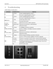
LED Status Indicators
LED Name Condition/Color
Meaning
On Green
Power is applied/supplied to Power 1.
P1
Off
No power is applied/supplied to Power 1
On Green
Power is applied/supplied to Power 2.
P2
Off
No power is applied/supplied to Power 2.
ALM (Alarm)
On Red Off
Power failure alarm occurs. No power failure alarm.
1,...
SISTP1040-551-LRT Install Guide Rev B - Page 21
Lantronix
SISTP1040-551-LRT Install Guide
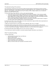
Troubleshooting Procedure
If the switch fails, isolate and correct the fault by determining the answers to the following questions and then taking the indicated action. First isolate the problem to the SISTP1040-551-LRT; troubleshoot any other network gear (e.g., other switches, remote devices such as IP cameras, WAPs, midspan injectors, etc.) to isolate...
SISTP1040-551-LRT Install Guide Rev B - Page 22

Lantronix
SISTP1040-551-LRT Install Guide
Regulatory ...digital device, pursuant to Part 15 of the FCC rules. These limits are designed to provide reasonable protection against harmful interference when the equipment is operated in a commercial environment. This equipment generates, uses and can radiate radio frequency energy and, if not installed and used in accordance with the instruction manual...