Intel R2000LH2/LT2 driver and firmware


Related Intel R2000LH2/LT2 Manual Pages
Download the free PDF manual for Intel R2000LH2/LT2 and other Intel manuals at ManualOwl.com
Service Guide - Page 5

... or BIOS defaults.
At the back of this document, you will find appendices on safety, "getting help", and warranty information.
Additional Information and Software
For additional information about this family of products or any of their supported accessories, refer to the following resources available at http://www.intel.com/p/en_US/support/.
Intel® Server System R2000LH2/LT2 Service Guide
v
Service Guide - Page 6

...® Server System.
For system firmware updates and onboard device drivers
Product Safety and Regulatory document
Use this Document or Software Intel® Server System R2000LH2/LT2 Family Technical Product Specification See the section on the web page titled, "Architecture/Specifications". Intel® Server System R2000LH2/LT2 Family Quick Installation User's Guide See the section on the web...
Service Guide - Page 7

... Wattage Limitation of the PCI Loading 3 Power Rating ...3 Server System Components...4 Hot Swap Hard Drive Bay and Front Panel Options 4 Front Panel ...5 Back Panel ...5 Server Board Components...6 System Recovery Jumpers...8 Peripheral Devices...9
2 Hardware Installations and Upgrades 13
Before You Begin...13 Tools and Supplies Needed ...13 System Reference ...13
Cable Routing...13 For system...
Service Guide - Page 14

... each installed power supply module
Riser Cards
Video
On-board storage controllers and options
Support for two riser card slots. Each riser card slot has support for three PCIe x16 slots Integrated 2D Video Controller 16 MB DDR3 Memory One low-profile eUSB 2x5 pin connector to support low-profile eUSB solid state devices Two single port SATA connectors capable...
Service Guide - Page 19

... USB port
BG (Option) RMM4 NIC connector
AA Password Clear jumper
BH (Option) TPM connector
AB BIOS Recover jumper
BI Serial A jumper
AC BIOS Default jumper
BJ BMC force update
AD ME Force Update jumper
AE CPU #1 DIMM slots - Memory Banks C and D
AF CPU #1 socket
AG CPLD programming header
Figure 7. Server Board Connector and Component Locations
Intel® Server System R2000LH2/LT2...
Service Guide - Page 21
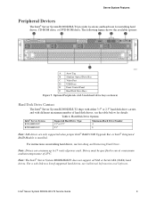
... Devices
The Intel® Server System R2000LH2/LT2 provides locations and hardware for installing hard drives, CD-ROM drive, or DVD-ROM drive. The following figure shows the available options:
A Asset Tag B Slimline Optical Drive Bay C Video Port D USB Ports E Front Control Panel F Hard Disk Drive Bays
Figure 9. Optional Peripherals (4x3.5-inch hard drive bays as shown)
Hard Disk Drive...
Service Guide - Page 25

... optional device connection.
For system with 4 x 3.5" hot swap hard drive bay
Note: 1. To activate the port SCU1 (4-7) on the server board, a proper Intel® RAID C600 Upgrade Key must be installed. For instructions, see Intel® RAID C600 Upgrade Key Installation Guide. 2. A second SSD is supported when the optical drive is NOT in use.
Intel® Server System R2000LH2/LT2 Service Guide...
Service Guide - Page 26

Hardware Installations and Upgrades
Figure 15. Cable Routing - 4 x 3.5" Hot Swap HDD
14
Intel® Server System R2000LH2/LT2 Service Guide
Service Guide - Page 27

... hot swap hard drive bay
Note: 1. To activate the port SCU1 (4-7) on the server board, a proper Intel® RAID C600 Upgrade Key must be installed. For instructions, see Intel® RAID C600 Upgrade Key Installation Guide. 2. A second SSD is supported when the optical drive is NOT in use.
Figure 16. Cable Routing - 8 x 2.5" Hot Swap HDD
Intel® Server System R2000LH2/LT2 Service Guide
15
Service Guide - Page 28

Hardware Installations and Upgrades
Fan Connections
Use the figures below to determine the proper fan connections.
Figure 17. System Fan Order
Figure 18. Connecting the Fan Power Cables to the Fan Board and PDB
16
Intel® Server System R2000LH2/LT2 Service Guide
Service Guide - Page 29

... Installations and Upgrades
Removing and Installing ...installing the bezel, you must install the rack handles. 1. Lock the right end of the front bezel to the rack handle (see letter A). 2. Rotate the front bezel clockwise till the left end clicks into place (see letter B). 3. Lock the bezel if needed.
Figure 20. Installing the Front Bezel
Intel® Server System R2000LH2/LT2 Service Guide...
Service Guide - Page 30

... the chassis (see letter B)
Figure 21. Removing the Front Fan Bezel
Installing the Front Fan Bezel
1. Slide in the bezel (see letter A). . 2. Secure the bezel to the chassis with the two screws on left and right end as shown (see
letter B).
Figure 22. Installing the Front Fan Bezel
18
Intel® Server System R2000LH2/LT2 Service Guide
Service Guide - Page 31

... system as shown.
Figure 23. Removing the Rack Handle
Installing the Rack Handles
Align the rack handle with the two holes on the side of the server system and attach the rack handle to the server system with two screws as shown.
Figure 24. Installing the Rack Handle
Intel® Server System R2000LH2/LT2 Service Guide
19
Service Guide - Page 32

... ensure proper cooling. You will need to remove the top cover to add or replace components inside of the server. Before removing the top cover, power down the server and unplug all peripheral devices and the power cable(s).
20
Intel® Server System R2000LH2/LT2 Service Guide
Service Guide - Page 33

... the cover back and lift upward.
Figure 27. Removing the System Cover
Installing the System Cover
1. Place system cover onto the chassis and slide forward to engage recessed edge at front of cover (see letter A).
2. Tighten the screw at front (see letter B).
Figure 28. Installing the System Cover
Intel® Server System R2000LH2/LT2 Service Guide
21
Service Guide - Page 34

... chassis (see letter B).
Figure 29. Removing the Front End Module
Installing the Front End Module
1. Push the front end module into place (see letter A). 2. Secure the front end module with six screws (see letter B).
Figure 30. Installing the Front End Module
3. Connect any required cables, please refer to Cable Routing.
22
Intel® Server System R2000LH2/LT2 Service Guide
Service Guide - Page 35
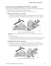
... PCI Riser Assembly
1. Position the riser card connector edge over the server board riser socket (see letter A). 2. Press down the release lever to install the riser assembly into the riser socket (see letter B). 3. Push on the board edge above the connector to ensure the connector is seated.
Figure 32. Installing the PCI Riser Assembly
Intel® Server System R2000LH2/LT2 Service Guide...
Service Guide - Page 41

...recommends using Processor Insertion/ Removal Tool (IPN: G21819-003) to install or replace the processor(s). Before removing or replacing the processor, please make sure following steps are performed. 1. Ensure the AC power cord(s) are disconnected from the system. 2. Remove the system cover. For instructions, see Removing the System Cover.
Intel® Server System R2000LH2/LT2 Service Guide
29
Service Guide - Page 80

...phone support on Intel® server boards, server chassis, server RAID controller cards, and Intel® Server Management.
Note: You must login in to the reseller site to obtain the 24x7 number.
Warranty Information
To obtain warranty information, visit the following Intel® website: http://www.intel.com/support/motherboards/server/sb/cs-010807.htm
68
Intel® Server System R2000LH2/LT2...
Service Guide - Page 83

... RAID controller firmware version: Has the latest RAID firmware been tried? (Yes/No): RAID driver version: Has the latest RAID driver been tried? (Yes/No): RAID volumes configuration (disks & RAID level): RAID volume use (Boot device/Data Volume): Is BBU (Battery Backup Unit) installed? (Yes/No): BBU part number:
Detailed description of issue:
Intel® Server System R2000LH2/LT2 Service Guide...