Gigabyte GA-6PXSVT driver and firmware


Related Gigabyte GA-6PXSVT Manual Pages
Download the free PDF manual for Gigabyte GA-6PXSVT and other Gigabyte manuals at ManualOwl.com
Manual - Page 5

Box Contents
GA-6PXSVT motherboard Driver CD Two SATA cables I/O Shield
• The box contents above are for reference only and the actual items shall depend on the product package you obtain. The box contents are subject to change without notice.
• The motherboard image is for reference only.
- 5 -
Manual - Page 7

... 3 slot 0) 8 pin power connector System fan #3 connector System fan #1connector System fan #2 connector SATA SGPIO header SATA port 1 DOM support jumper
BIOS Upgrade ROM SATA port 0 DOM support jumper SATA 6Gb/s connectors SATA 3Gb/s connectors Battery socket Chassis intrusion jumper Clear CMOS jumper Clear password jumper Front panel header USB Type A connector
Back plane board header
- 7 -
Manual - Page 8

...connectors BIOS Write Protect jumper USB 3.0 header USB 2.0 header Serial port cable header BMC Upgrade ROM TPM module connector LAN3 active LED ASPEED AST2400VB chipset BMC readiness LED ME Recovery jumper PCIE1 and PCIE2 bandwidth switch
jumper PCI-E x8 slot (x8 bandwidth/Shared
bamdwidth with PCIE_2 slot) PMBus Select jumper Force to Stop FRB3 Timer jumper PCI-E x16 slot PCI-E x16 slot S3 Power...
Manual - Page 10

... a motherboard, CPU or memory. If you do not have an ESD wrist strap, keep your hands dry and first touch a metal object to eliminate static electricity. • Prior to installing the motherboard, please have it on top of an antistatic pad or within an electrostatic shielding container. • Before unplugging the power supply cable from the motherboard, make...
Manual - Page 11

... back panel) 1 x USB 2.0 Type A connector 1 x 24-pin ATX main power connector 1 x 8-pin ATX 12V power connector 10 x SATA 6Gb/s connectors 4 x SATA 3Gb/s connectors 1 x CPU fan header 4 x System fan header 1 x Front panel header 1 x Back plane borad header 1 x USB3.0 header 1 x USB2.0 header 1 x TPM header 1 x Serial port header 1 x PMBus header 1 x SATA SGPIO header
- 11 -
Hardware Installation
Manual - Page 12

... ŠŠ CPU overheating warning ŠŠ CPU/System/Power fan fail warning ŠŠ CPU/System fan speed control ŠŠ 1 x 64 Mbit flash ŠŠ AMI BIOS
ŠŠ ATX Form Factor; 12 inch x 9.6 inch
* GIGABYTE reserves the right to make any changes to the product specifications and product-related information without prior notice.
Hardware Installation
- 12 -
Manual - Page 13

... not recommended
that the system bus frequency be set beyond hardware specifications since it does not meet the standard requirements for the peripherals. If you wish to set the frequency beyond the standard specifications, please do so according to your hardware specifications including the CPU, graphics card, memory, hard drive, etc.
1-3-1 Installing the CPU
A. Locate the alignment keys on...
Manual - Page 14

... steps below to correctly install the CPU into the motherboard CPU socket. •• Before installing the CPU, make sure to turn off the computer and unplug the power cord from the power outlet to prevent damage to the CPU. •• To protect the socket contacts, do not remove the protective plastic cover unless the CPU is inserted into the...
Manual - Page 15

... you begin to install the memory: • Make sure that the motherboard supports the memory. It is recommended that memory of the
same capacity, brand, speed, and chips be used. • Always turn off the computer and unplug the power cord from the power outlet before installing
the memory to prevent hardware damage. • Memory modules have a foolproof design. A memory module can be...
Manual - Page 16

1-4-2 Installing a Memory
Before installing a memory module, make sure to turn off the computer and unplug the power cord from the power outlet to prevent damage to the memory module. Be sure to install DDR3 DIMMs on this motherboard.
Installation Step: Step 1. Insert the DIMM memory module vertically into the DIMM slot, and push it down. Step 2. Close the plastic clip at both edges...
Manual - Page 17

... Gigabit Ethernet LAN port provides Internet connection at up to 1 Gbps data rate. The following describes the states of the LAN port LEDs. USB 3.0 Port The USB port supports the USB 3.0 specification. Use this port for USB devices such as a USB keyboard/mouse, USB printer, USB flash drive and etc. ID Switch Button This button provide the selected unit idenfication function.
Hardware Installation...
Manual - Page 18

...
Link between system and network or no
access
Blinking Data transmission or receiving is occurring
Off
No data transmission or receiving is occurring
• When removing the cable connected to a back panel connector, first remove the cable from your device and then remove it from the motherboard.
• When removing the cable, pull it straight out...
Manual - Page 19

...12
26 11
23 25 22
21
15
24
33 34
14
10
96
45
2
1) ATX1 2) P1_CPU 3) CPU_FAN1 (CPU Fan) 4) SYS_FAN1 (System Fan) 5) SYS_FAN3 (System Fan) 6) SYS_FAN2 (System Fan) 7) SYS_FAN4 (System Fan) ... 12) SATA10/11/12/13 13) TPM 14) F_PANEL1 15) BP_1 16) F_USB3_1 17) F_USB1
Hardware Installation
18) COM2 19) LAN3_ACT 20) BMC_LED1 21) SATA_SGPIO 22) BAT1 23) CLR_CMOS1 24) PASSWORD1 25) CASE_OPEN1...
Manual - Page 20

... the connectors you wish to connect. • Before installing the devices, be sure to turn off the devices and your computer. Unplug the power
cord from the power outlet to prevent damage to the devices. • After installing the device and before turning on the computer, make sure the device cable has
been securely attached to the connector on the motherboard.
Hardware Installation
- 20 -
Manual - Page 21
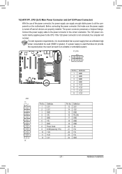
... on the motherboard. Before connecting the power connector, first make sure the power supply is turned off and all devices are properly installed. The power connector possesses a foolproof design. Connect the power supply cable to the power connector in the correct orientation. The 12V power connector mainly supplies power to the CPU. If the 12V power connector is not connected, the computer will...
Manual - Page 22

... ground wire). The motherboard supports CPU fan speed control, which requires the use of a CPU fan with fan speed control design. For optimum heat dissipation, it is recommended that a system fan be installed inside the chassis.
SYS_FAN4
CPU_FAN1
1 1
SYS_FAN2
SYS_FAN3
SYS_FAN1
Pin No. 1 2 3 4
Definition GND +12V Sense Speed Control
• Be sure to connect fan cables to the fan...
Manual - Page 29

... (SATA SGPIO Header)
SGPIO stands for Serial General Purpose Input/Output which is a 4-signal (or 4-wire) bus used between a Host Bus Adapter (HBA) and a backplane. Out of the 4 signals, 3 are driven by the HBA and 1 is driven by the backplane. Typically, the HBA is a storage controller located inside a server, desktop, rack or workstation computer that interfaces with Hard disk drives (HDDs...
Manual - Page 39

... setup utility was created. EC Firmware Version Display version number of the Firmware setup utility. Processor Information CPU Type/ Max CPU Speed/ CPU Signature / Processor Cores / Microcode Patch Displays the technical specifications for the installed processor. Memory Information Total Memory / Current Memory Speed Displays the technical specifications for the installed memory. System Date Set...
Manual - Page 46

... is enabled, multi-threaded software applications can execute their threads, thereby improving performance. Options available: Enabled/Disabled. Default setting is Enabled.
Displays the technical specifications for the installed processor. Active Processor Cores (Note) Allows you to determine whether to enable all CPU cores. Options available: All/1/2/3. Default setting is All. Limit CPUID...
Manual - Page 49

... value 7 into MSR_ENERGY_PERFORMANCE_BIAS Balanced Energy: Write value 11 into MSR_ENERGY_PERFORMANCE_BIAS Energy Efficient: Write value 15 into MSR_ENERGY_PERFORMANCE_BIAS Default setting is Performance.
(Note)
This item is present only if you install a CPU that supports this feature. For more information about
Intel CPUs' unique features, please visit Intel's website.
- 49 -
BIOS Setup