Biostar P4M80-M7A V7.X driver and firmware
Drivers and firmware downloads for this Biostar item


Related Biostar P4M80-M7A V7.X Manual Pages
Download the free PDF manual for Biostar P4M80-M7A V7.X and other Biostar manuals at ManualOwl.com
P4M80-M7A user's manual - Page 1
...digital device, pursuant to Part 15 of the FCC Rules. These limits are designed to provide reasonable protection against harmful interference in a residential installation.... This equipment generates, uses and can radiate radio frequency energy and, if not installed and used in accordance with the instructions...content of this user's manual is subject to be changed without notice and we ...
P4M80-M7A user's manual - Page 2

... A (Rev 7.0 8
1.8
Components: P4M800-M7 A (Rev 7.0 9
Chapter 2:
2.1 2.2 2.3 2.4
Hardware Installation 10
Central Processing Unit (CPU 10 FAN Headers 11 Memory Module Installation 12 Connectors and Slots 13
Chapter 3: Headers & Jumpers Setup 14
3.1
How to Setup Jumpers 14
3.2
Detail Settings 14
Chapter 4: Useful Help 18
4.1
Award BIOS Beep Code 18
4.2
Extra Information 18...
P4M80-M7A user's manual - Page 5

...IDE connectors support 4 hard disk devices. 2 serial ATA connectors support 2 SATA devices.
Rear Side Connectors 4 USB 2.0 ports. 1 VGA port. 1 serial port. 1 parallel port. 1 RJ-45 LAN jack. 1 PS/2 Mouse & Keyboard port. 1 vertical audio port including 1 line-in connector, 1 line out connector, and 1 MIC in connector.
PS/2 Mouse PS/2 Keyboard
Printer Port
COM1
VGA1
LAN
USB x2
USB x2
Line...
P4M80-M7A user's manual - Page 12

P4M800-M7 & P4M800-M7 A
CHAPTER 2: HARDWARE INSTALLATION
2.1 CENTRAL PROCESSING UNIT (CPU)
Special Notice:
Remove Pin Cap before installation, and make good preservation for future use. When the CPU is removed, cover the Pin Cap on the empty socket to ensure pin legs won't be damaged.
Pin Cap
Step 1: Pull the lever sideways away ...
P4M80-M7A user's manual - Page 13

... installation.
2.2 FAN HEADERS
These fan headers support cooling-fans built in the computer. The fan wiring and plug may be different according to the fan manufacturer. Connect the fan cable to the connector while matching the black wire to pin#1.
CPU FAN Header: JCFAN1
Pin
Assignment
1
Ground
2
Power (+12V)
1
JCFAN1
3
FAN RPM rate sense
4
Smart Fan Control...
P4M80-M7A user's manual - Page 14

P4M800-M7 & P4M800-M7 A
2.3
1.
MEMORY MODULE INSTALLATION
Unlock a DIMM slot by pressing the retaining clips outward. Align a DIMM on the slot ... safety, if you need to change DDR modules, firstly, please unplug the 20-pin power cable with the power connector, and then you can change the modules. Afterwards, plug in the cable the power connector again, and finally you can boot up the system.
12
P4M80-M7A user's manual - Page 20

... beep when system boot-up Long beeps every other second
Meaning Video card not found or video card memory bad CPU overheated System will shut down automatically No error found during POST No DRAM detected or install
4.2 EXTRA INFORMATION
A. BIOS Update After you fail to update BIOS or BIOS is invaded by virus, the Boot-Block function will help to restore...
P4M80-M7A user's manual - Page 22

... snaps into place.
System does not boot from hard disk 1. drive, can be booted from optical drive.
Check cable running from disk to disk controller board. Make sure both ends are securely plugged in; check the drive type in the standard CMOS setup.
2. Backing up the hard drive is extremely important. All hard disks are capable of breaking down at any time.
System...
P4M80-M7A user's manual - Page 23

.... Also, in the About panel, you can get detail descriptions about BIOS model and chipsets. In addition, the frequency status of CPU, memory, AGP and PCI along with the CPU speed are synchronically shown on our main panel. Moreover, to protect users' computer systems if the setting is not appropriate when testing and results in system fail or...
P4M80-M7A user's manual - Page 24

... dialog will pop up. Please click "Next" button and follow the default procedure to install.
2. When you see the following dialog in setup procedure, it means setup is completed. If the "Launch the WarpSpeeder Tray Utility" checkbox is checked, the Tray...The following figures are just only for reference, the screen printed in this user manual will change according to your motherboard on hand.
22
P4M80-M7A user's manual - Page 25

P4M800-M7 & P4M800-M7 A
5.4 [WARPSPEEDER™] INCLUDES 1 TRAY ICON AND 5 PANELS
1. Tray Icon: Whenever the Tray Icon utility is launched, it will display a little tray icon on the right side of Windows Taskbar.
This utility is responsible for conveniently invoking [WarpSpeeder™] Utility. You can use the mouse by clicking the left button...
P4M80-M7A user's manual - Page 26
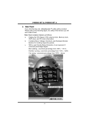
..., [WarpSpeeder™] utility will be invoked. Please refer to the following figure; the utility's first window you will see is Main Panel. Main Panel contains features as follows: a. Display the CPU Speed, CPU external clock, Memory clock,
AGP clock, and PCI clock information. b. Contains About, Voltage, Overclock, and Hardware Monitor
Buttons for invoking respective panels. c. With...