Asus AP3000 driver and firmware


Related Asus AP3000 Manual Pages
Download the free PDF manual for Asus AP3000 and other Asus manuals at ManualOwl.com
Hardware Reference - Page 2
... are released for each product design represented by the digit before and after the period of the manual revision number. Manual updates are represented by the third digit in the manual revision number.
For previous or updated manuals, BIOS, drivers, or product release information, contact ASUS at http://www.asus.com.tw or through any of the means indicated on the following...
Hardware Reference - Page 4

... BIOS Setup 16
IV. Hardware Setup 4-1. Opening the Chassis 17 Panel Screws 17 Removing the Right Panel 17 Opening the Left Panel 18 Chassis Circulation System 18 Fan Modules 18 4-2. Rear Cooling Fan Control Board 19 Rear Cooling Fan Control Board Settings 19 4-3. Motherboard 20 Motherboard Spacers 20 Install the Baseboard 20 Motherboard Screws 20 Device Cables 21 Cable Connections...
Hardware Reference - Page 6
... for a Class B digital device, pursuant to Part 15 of the FCC Rules. These limits are designed to provide reasonable protection against harmful interference in a residential installation. This equipment generates, ...the dealer or an experienced radio/TV technician for help.
WARNING! The use of shielded cables for connection of the monitor to the graphics card is required to assure compliance with...
Hardware Reference - Page 7
...computers. You should also read all documentation and manuals included with this server and with your separately purchased components.
• 1-1. How this Manual is Organized
There are only a few sections in this reference guide...PHILIP (CROSS) SCREW DRIVER: Tools required to install or remove the components in this server. STANDARD (FLAT) SCREW DRIVER: Tools required to install or remove the ...
Hardware Reference - Page 10

... or disconnecting any devices.
Operation Safety
IMPORTANT
• Any operation on this server must be conducted by certified or experienced engineers.
• Before operating your server, carefully read all the manuals included with the server package.
• Before using the server, make sure all cables are correctly connected and the power cables are not damaged...
Hardware Reference - Page 11
... electrical potentials.
CAUTION
This product is equipped with a three-wire power cable and plug for the user's safety. Use the power cable in conjunction with a properly grounded electrical outlet to avoid electrical shock.
IMPORTANT
Motherboards, adapters, and disk drives are sensitive to static electricity discharge. These devices are wrapped in antistatic bags to prevent this damage. Take the...
Hardware Reference - Page 16

... any pre-installed software. When booting your server for the first time, make BIOS settings by following the motherboard User's Manual.
NOTE When installing Windows NT 4.0, use the Windows NT installation disks. Installing from the CD will require you to pre-install SCSI drivers by pressing F6 before setup begins. You may need device drivers on a floppy disk in order to install devices during the...
Hardware Reference - Page 17
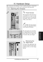
IV. Hardware Setup
This section gives descriptions of how to install and remove components. When setting up devices on the server, perform the following steps.
• 4-1. Opening the Chassis
Panel Screws
The top panel on the chassis is...
To remove the right panel, the front door must be removed by pushing down on the hinge spring.
IV. Hardware Setup
Opening the Chassis
AP 3000 Hardware Reference...
Hardware Reference - Page 19

... of the server and to the ASMA software. The fan control board's cable connections are shown below.
Fan
Fan Power Connectors
Reserved Connector
Fan Status Signal Connector
Power Input Connector
Fan Control Settings
Reserved Fan Connectors
Rear Cooling Fan Control Board Settings
The rear fan control board has DIP switches to allow controlling the control board status and the number of fans.
DIP...
Hardware Reference - Page 20

IV. Hardware Setup
• 4-3. Motherboard
You can remove the extended expansion card guide before installing or removing the motherboard. All screws are necessary to provide the needed stabilization to support all the motherboard expansion cards used in this chassis.
Motherboard Spacers
Place four spacers in the areas circled on the chassis.
Extended Expansion Card Guide
Spacer
Place and ...
Hardware Reference - Page 22

.... One retention module can have one Xeon processor installed. Before installing the CPU, secure the motherboard on the rubber pad and metal baseboard. (See p. 20.)
When only one processor is used, the other Slot 2 connector must be terminated with the provided front side bus termination module.
For memory installation, refer to the motherboard User's Manual.
Single Dot
Captive Nut Long Screw...
Hardware Reference - Page 23

...processor. The lifters clamp on to the cartridge on the two holes at the top of each corner.
For the lock bar, there is a left and a
right side. The left side has a single
dot and the right side has
two dots (when holding
the motherboard... Dot
IV. Hardware Setup
CPU
Install Retention Mechanism Frame
A metal frame is used accross both retention mechanisms. After installing the frame, four ...
Hardware Reference - Page 24
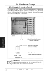
... chassis provides a micro toggle switch that must be connected to the motherboard for the chassis intrusion detection to work. The motherboard will signal the ASMA software when the side panel is opened. The connection diagram is given here.
IV. Hardware Setup
Chassis Intrusion Switch
Cable
Chassis Intrusion Switches (one on each side)
from the two...
Hardware Reference - Page 25
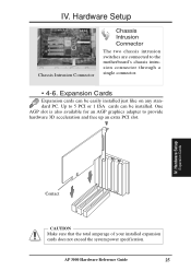
... the motherboard's chassis intrusion connector through a single connector.
• 4-6. Expansion Cards
Expansion cards can be easily installed just like on any standard PC. Up to 5 PCI or 1 ISA cards can be installed. One AGP slot is also available for an AGP graphics adapter to provide hardware 3D acceleration and free up an extra PCI slot.
IV. Hardware Setup
Expansion Cards
Contact...
Hardware Reference - Page 27

....
IV. Hardware Setup
Fixed Storage Devices
Fixed Device Bay Cover
After releasing the device bay cover clips, pry the cover away from the chassis using a screw driver from the front.
Storage Device Spacers
A floppy drive spacer is used to cover the floppy drive and power button. A standard storage device spacer is used to cover the CDROM, tape drive, or additional CD-ROMs. You should purchase...
Hardware Reference - Page 29

...tray. To remove the tray, extend both levers and pull on both levers. To install the tray, push the tray firmly into the bay with the levers extended, then close the levers.
IV. Hardware Setup
Hot-Swap Bay
Hot-Swap Bay
To remove the hot-swap bay, release the front... screws as circled above and then the entire hot-swap bay can be slid out of the chassis.
AP 3000 Hardware Reference Guide
29
Hardware Reference - Page 30

... secured by four screws on each fan. The ASMA software will report an error message when any of these two fans malfunctions.
Front Cooling Fan Control Board (mounted with the component side facedown)
ß,§,
Lower Fan
Upper Fan
IV. Hardware Setup
Front Cooling Fans
Hard Disk Drive Message Board (LEDs)
IMPORTANT Usually, the rotation of the fan...
Hardware Reference - Page 34

... other SCSI device. SCSI devices vary in how they set the ID number. Refer to the product manual for any additional devices that you may install for details on how to set its ID number.
• 4-13. Expansion Card Guide
The chassis provides an adjustable expansion card guide to help hold expansion cards in their slots.
Knob
Metal Arm
Securing Expansion Card Guide
The expansion card guide is...
Hardware Reference - Page 40

... to setup a new non-RAID hard disk drive before formatting and installing an operating system.
IDE (Integrated Drive Electronics) IDE devices integrate the drive control circuitry directly on the drive itself, eliminating the need for a separate adapter card (in the case for SCSI devices). UltraDMA/33 IDE devices can achieve up to 33MB/Sec transfer.
LPT Port (Line Printer Port) Logical device name...
Hardware Reference - Page 41
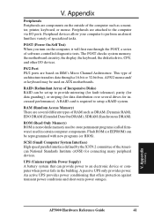
... several drives for increased performance). A RAID card is required to setup a RAID system.
RAM (Random Access Memory) There are several different types of RAM such as DRAM (Dynamic RAM), EDO DRAM (Extended Data Out DRAM), SDRAM (Synchronous DRAM).
ROM (Read Only Memory) ROM is nonvolatile memory used to store permanent programs (called firmware) used in certain computer components. Flash ROM (or...