Asus AP200 driver and firmware


Related Asus AP200 Manual Pages
Download the free PDF manual for Asus AP200 and other Asus manuals at ManualOwl.com
Hardware Reference - Page 2
... are released for each product design represented by the digit before and after the period of the manual revision number. Manual updates are represented by the third digit in the manual revision number.
For previous or updated manuals, BIOS, drivers, or product release information, contact ASUS at http://www.asus.com.tw or through any of the means indicated on the following...
Hardware Reference - Page 4

...
2-2. Chassis Features 15 5.25" Device Cage 15 3.5" Device Cage 15 Hard Disk Drive Carrier Plate above the Power Supply ... 15 Power Supply 15 Air Circulation System 15 System Speaker 15 Long Card Guide 15
III. Getting Started
3-1. Starting the Server 16 3-2. LED Indicators 16 3-3. BIOS Setup 16
IV. Hardware Setup
4-1. Chassis 17 Removing the Left Panel 17 Installing the Left Panel 17...
Hardware Reference - Page 6

... void the user's authority to operate this equipment.
Canadian Department of Communications Statement
This digital apparatus does not exceed the Class B limits for radio noise emissions from digital apparatus set out in the Radio Interference Regulations of the Canadian Department of Communications.
This class B digital apparatus complies with Canadian ICES-003.
6
AP200 Hardware Reference Guide
Hardware Reference - Page 7

... Drive: Floppy Drive: Cables: SCSI Terminator: User's Manuals: Drivers/Utilities:
ASUS AS-10 Tower 250W ATX ASUS P2B-DS/P2B-D ASUS 40X 1.44MB Power, IDE, floppy, 50- & 68-pin SCSI, CD audio cables Terminators for 68-pin Ultra2 SCSI cables CD-ROM, SCSI, Motherboard SCSI, CD-ROM, Motherboard
ASUS RAID Card Solutions (you may purchase from ASUS)
PCI-DA2100A:
Ultra-Wide SCSI dual-channel RAID card...
Hardware Reference - Page 9
... scrapes. • When the server is powered on, heat sinks and the surfaces of certain IC devices may be hot. Do not touch them. Check whether the fans are functioning properly.
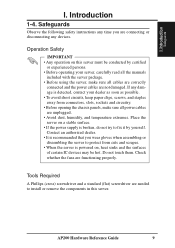
Tools Required
A Phillips (cross) screwdriver and a standard (flat) screwdriver are needed to install or remove the components in this server.
AP200 Hardware Reference Guide
9
Hardware Reference - Page 10
....
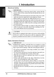
CAUTION
This product is equipped with a three-wire power cable and plug for the user's safety. Use the power cable in conjunction with a properly grounded electrical outlet to avoid electrical shock.
Static-Sensitive Devices
IMPORTANT Motherboards, adapters, and disk drives are sensitive to static electricity discharge. These devices are wrapped in antistatic bags to prevent this damage...
Hardware Reference - Page 11

... CPU, memory, hard disk drives, and expansion cards. Use this hardware reference guide along with your motherboard's User's Manual in order to complete the installations.
4. Connect a keyboard and a mouse (purchased separately). 5. Connect a VGA-compatible monitor (purchased separately). 6. Connect a printer to the parallel port if desired. 7. Connect the server to a network. (An optional network...
Hardware Reference - Page 12
II. Components
Front View
II. Components
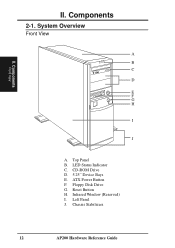
2-1. System Overview
Front View
A B C
D
E F G H
I
J
A. Top Panel B. LED Status Indicator C. CD-ROM Drive D. 5.25" Device Bays E. ATX Power Button F. Floppy Disk Drive G. Reset Button H. Infrared Window (Reserved) I. Left Panel J. Chassis Stabilizers
12
AP200 Hardware Reference Guide
Hardware Reference - Page 16

... not come with any pre-installed software. When booting your server for the first time, make BIOS settings by following the motherboard User's Manual.
NOTE When installing Windows NT 4.0 or higher operation system, use the Windows NT installation floppy disks. Installing from the CD will require you to pre-install SCSI drivers by pressing before Setup begins.
16
AP200 Hardware Reference Guide
Hardware Reference - Page 17
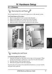
... left panel outward from the bottom.
IV. HW Setup
Chassis
Thumb Screw Location
Pulling the Left Panel Backward Pulling the Bottom of the Left Panel
(Step 3)
(Step 4)
Installing the Left Panel
Left Panel Installation Procedure: 1. Hang the left panel on the hooks... the server chassis from unauthorized intrusion, you may lock the left panel with a padlock.
AP200 Hardware Reference Guide
17
Hardware Reference - Page 18
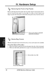
... the front panel removed, the device bay covers can be removed or installed. Device Bay Removal Procedure: 1. With your thumb, push the tab outward against the side of the front panel. 2. With your other hand, push the device cage cover inward from the front side.
Device Bay Cover Tab
Front Panel Backside
18
AP200 Hardware Reference Guide
Hardware Reference - Page 20

... Setup
Motherboard
P2B-D/DS Chassis Intrusion Photo Sensor
Panel Connections
Several wires should be connected to the motherboard for the IDE/SCSI activity, power, and message indicators on the front panel. Panel connections also allow for an ATX power button, reset switch, and speaker. Connect the chassis front panel wires as illustrated:
Button Cell Battery for motherboard BIOS...
Hardware Reference - Page 21
... Lever
IV. HW Setup
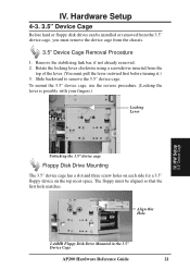
3.5" Device Cage
Unlocking the 3.5" device cage
Floppy Disk Drive Mounting
The 3.5" device cage has a slot and three screw holes on each side for a 3.5" floppy device on the top most space. The floppy must be aligned so that the first hole matches.
Align this Hole.
1.44MB Floppy Disk Drive Mounted in the 3.5" Device Cage
AP200 Hardware Reference Guide
21
Hardware Reference - Page 22
... alignment and insertion is made.
IV. HW Setup
5.25" Device Cage
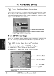
Red stripe of signal cable Red stripe of power cable 1.44MB Floppy Disk Drive Connections
4-4. 5.25" Device Cage
Before CD-ROM, tape, or hard disk drives can be installed or removed from the 5.25" device cage, you must remove the device cage from the chassis.
5.25" Device Cage Removal Procedure
1. Rotate the locking lever...
Hardware Reference - Page 23

IV. Hardware Setup
CD-ROM Drive Mounting and Connections
The CD-ROM disk drive mounts only in the 5.25" device cage and requires signal and power connections. The red stripe of the signal and power cables should face each other.
CD Audio Output
CD-ROM Drive Connections
NOTE: A CD-ROM audio cable is also provided in case you install an audio card. The only function of the audio cable is to allow...
Hardware Reference - Page 27
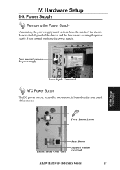
... the power supply. Press inward to release the power supply.
Press inward to release the power supply.
Power Supply Unmounted
ATX Power Button
The DC power button, secured by two screws, is located on the front panel of the chassis.
Power Button Screws
IV. HW Setup
Power Supply
Buttons on the Front Panel
Reset Button
Infrared Window (reserved)
AP200 Hardware Reference Guide...