Asus AP160R-S driver and firmware

Related Asus AP160R-S Manual Pages
Download the free PDF manual for Asus AP160R-S and other Asus manuals at ManualOwl.com
User Guide - Page 2
... are released for each product design represented by the digit before and after the period of the manual revision number. Manual updates are represented by the third digit in the manual revision number.
For previous or updated manuals, BIOS, drivers, or product release information, contact ASUS at http://www.asus.com.tw or through any of the means indicated on the following...
User Guide - Page 3

...Chapter 2: Hardware Setup 17
2.1 Removing and installing the chassis cover 18 Removing the cover 18 Installing the cover 18
2.2 Motherboard Placement 19 Placement Direction 19 Motherboard Screws 19
2.3 Installing a CPU 20 CPU Orientation 20 CPU Socket Location 20 Unlock the CPU Socket 21 Insert the CPU 21 Secure the CPU 21 Install the Heatsink 22
2.4 Installing system memory 23 DIMM...
User Guide - Page 4
... boards 24 Bridge board 24 Backplane board 25
2.6 Installing a hard disk drive 26 2.7 Installing a PCI card 28 2.8 Installing the front bezel and rack ears 30 2.9 Installing CD-ROM and floppy drives 31
Chapter 3: Hardware Options 33
3.1 Cooling System 34 Fan locations 34 Fan connectors 34 Fan cable connections 35 Removing the fans 36
3.2 Power connections 37 3.3 Removing the power...
User Guide - Page 6
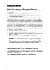
... for a Class B digital device, pursuant to Part 15 of the FCC Rules. These limits are designed to provide reasonable protection against harmful interference in a residential installation. This equipment generates, ...the dealer or an experienced radio/TV technician for help.
WARNING! The use of shielded cables for connection of the monitor to the graphics card is required to assure compliance with...
User Guide - Page 7
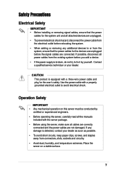
...; Before installing or removing signal cables, ensure that the power
cables for the system unit and all attached devices are unplugged. • To prevent electrical shock hazard, disconnect the power cable from
the electrical outlet before relocating the system. • When adding or removing any additional devices to or from the
system, ensure that the power cables for the devices are...
User Guide - Page 10
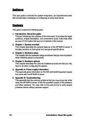
... information that are not contained in this manual.
2. Chapter 1: System overview This chapter describes the general features of the AP160R-S server. It includes sections on front panel and rear panel specifications.
3. Chapter 2: Hardware setup This chapter lists the hardware setup procedures that you have to perform when installing system components.
4. Chapter 3: Hardware options This chapter...
User Guide - Page 11
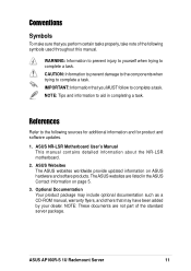
...sources for additional information and for product and software updates.
1. ASUS NR-LSR Motherboard User's Manual This manual contains detailed information about the NR-LSR motherboard.
2. ASUS Websites The ASUS websites worldwide provide updated information on ASUS hardware and softare products. The ASUS websites are listed in the ASUS Contact Information on page 5.
3. Optional Documentation Your...
User Guide - Page 12
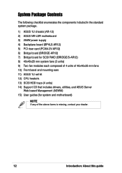
...-LSR motherboard 3) 284W power supply 4) Backplane board (BP4LS-AR12) 5) PCI riser card (PCI64-3V-AR12) 6) Bridge board (BRIDGE-AR12) 7) Bridge board for SCSI RAID (BRIDGE/S-AR12) 8) 40x40x28 mm system fans (3 units) 9) Two fan modules each composed of 4 units of 40x40x28 mm fans 10) Front bezel and mounting ears 11) ASUS 1U rail kit 12) CPU heatsink 13) SCSI HDD trays (4 units) 14) Support...
User Guide - Page 16
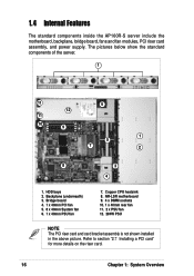
... inside the AP160R-S server include the motherboard, backplane, bridge board, fans and fan modules, PCI riser card assembly, and power supply. The pictures below show the standard components of the server.
1
11
6
12
11
10 9
1 5
7
2
8
3
4
1. HDD bays 2. Backplane (underneath) 3. Bridge board 4. 1 x 40mm PCI fan 5. 8 x 40mm System fan 6. 1 x 40mm PSU fan
7. Copper CPU heatsink 8. NR...
User Guide - Page 17

Chapter 2
This chapter describes the hardware setup procedures that you have to perform when installing system components.
Hardware Setup
ASUS AP160R-S 1U Rackmount Server
17
User Guide - Page 18

... the cover, push the two latches outward, then slide the cover towards the rear for about half an inch.
2. Lift the cover from the chassis.
Installing the cover
1. Place the cover on top of the chassis leaving about half an inch gap from the front edge.
Half-inch gap
2. Firmly hold...
User Guide - Page 19

... above) on the serial port, VGA port, and high-density SCSI connector before installing or removing the motherboard. Otherwise, you cannot properly install or remove the motherboard.
Motherboard Screws
Place seven (7) screws in the holes indicated by circles to secure the motherboard to the chassis. Do not overtighten the screws. Doing so may damage the motherboard.
ASUS AP160R-S 1U Rackmount...
User Guide - Page 20

...motherboard supports an Intel Pentium 4 processor. This section tells you how to install a CPU. Refer to the motherboard user guide for more information.
CPU Socket Location
Locate the 478-pin CPU socket and note the Pin 1 location.
Pin 1
CPU Orientation
A CPU... of the CPU to Pin 1 on the socket.
Gold Mark
CAUTION
Incorrect installation of the CPU into the socket may bend the pins and ...
User Guide - Page 22

NOTE
You must remove the riser card module and card bracket assembly before installing or removing the heatsink.
Install the Heatsink
1. Carefully place the heatsink on top of the installed CPU. The heatsink fits in only one orientation. Take note of the heatsink placement as shown (ASUS logo facing the rear panel).
2. Hold down the heatsink lightly and...
User Guide - Page 23

2.4 Installing system memory
DIMM sockets location
The motherboard has four Dual Inline Memory Module (DIMM) sockets that support up to 8GB system memory using registered ECC PC2100/PC1600 DDR DIMMs.
DDR DIMM sockets
Install a DIMM
1. Unlock a DIMM socket by pressing the retaining clips ...clips outward to unlock the DIMM.
2. Remove the DIMM from the socket.
ASUS AP160R-S 1U Rackmount Server
23
User Guide - Page 24
...).
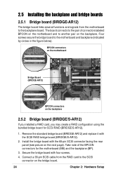
2. Install the bridge board with the 68-pin SCSI connector facing the rear panel (see picture on the next page). Take note of the BPCON connectors for the motherboard (MB) and the backplane (BP).
3. Secure the bridge board with four screws.
4. Connect a 68-pin SCSI cable from the RAID card to the SCSI connector on the bridge board.
24
Chapter 2: Hardware Setup
User Guide - Page 25

When installed, the SCSI RAID bridge board appears as shown below.
Bridge Board (BRIDGE/S-AR12)
2.5.3 Backplane board
The backplane board includes the four hot-swappable connectors for the SCSI drives accessible from the front panel, and several other connectors that link to the motherboard and main power supply unit.
The backplane board comes pre-installed in the chassis. Normally, you do not ...
User Guide - Page 26

2.6 Installing a hard disk drive
1. Push the thumb pad all the way to the right to release the HDD tray.
2. Pull out the tray handle then pull the tray out of the chassis.
3. Secure a hard disk drive to the tray using four screws.
4. After securing the drive to the tray, carefully insert the tray into the drive bay.
26
Chapter 2: Hardware Setup
User Guide - Page 28
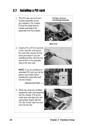
... installing an extended PCI card, pull up the plastic card holder before installing the assembly back into the chassis.
Extended Card Holder
3. When the cards are installed, replace the riser card assembly into the chassis. Pull up the metal lever and align the riser card golden fingers with the PCI slot. Firmly insert the riser card into the slot.
28
Chapter 2: Hardware Setup
User Guide - Page 31
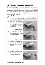
2.9 Installing CD-ROM and floppy drives
The slim-type CD-ROM drive and slim-type floppy drive are contained in an external combo drive cage. You will need these drives when installing the drivers, utilities, and software applications. The drives are not hot-swappable so you should install them before powering up the system. However, you can detach the cage from the chassis when you...