Asus AP130 driver and firmware


Related Asus AP130 Manual Pages
Download the free PDF manual for Asus AP130 and other Asus manuals at ManualOwl.com
AP130 User Manual English Edition - Page 2

... are released for each product design represented by the digit before and after the period of the manual revision number. Manual updates are represented by the third digit in the manual revision number.
For previous or updated manuals, BIOS, drivers, or product release information, contact ASUS at http://www.asus.com.tw or through any of the means indicated on the following...
AP130 User Manual English Edition - Page 3
... 17
Chapter 2: Hardware Setup 19
2.1 Remove the Chassis Cover 20 Unlock the side cover 20 Remove the side cover 20
2.2 Motherboard Placement 21 Placement Direction 21 Motherboard Screws 21
2.3 Install a CPU 22 CPU Socket Location 22 CPU Orientation 22 Unlock the CPU Socket 23 Insert the CPU 23 Secure the CPU 23 Install the Fan Heatsink Assembly 24
2.4 Install System Memory 26 DIMM...
AP130 User Manual English Edition - Page 4

Contents
2.5 Install a Hard Disk Drive 27 Remove the HDD/Floppy Cage 27 Install the HDD 28 Connect the Cables 28
2.6 Replace the Cover 29 Re-install the Cover 29
Chapter 3: Powering Up 31
3.1 Getting Started 32 Connect a Monitor 32 Connect the Power Cord 32 Power On 32 Check Power Status 32
Appendix A: Power Supply 33
A.1 General Description 34 A.2 Specifications 35
Input ...
AP130 User Manual English Edition - Page 6
... for a Class B digital device, pursuant to Part 15 of the FCC Rules. These limits are designed to provide reasonable protection against harmful interference in a residential installation. This equipment generates, ...the dealer or an experienced radio/TV technician for help.
WARNING! The use of shielded cables for connection of the monitor to the graphics card is required to assure compliance with...
AP130 User Manual English Edition - Page 7
...; Before installing or removing signal cables, ensure that the power
cables for the system unit and all attached devices are unplugged. • To prevent electrical shock hazard, disconnect the power cable from
the electrical outlet before relocating the system. • When adding or removing any additional devices to or from the
system, ensure that the power cables for the devices are...
AP130 User Manual English Edition - Page 10

... that are not contained in this manual.
2. Chapter 1: System Overview This chapter describes the general features of the AP130 server. It includes sections on front panel and rear panel specifications.
3. Chapter 2: Hardware Setup This chapter lists the hardware setup procedures that you have to perform when installing system components.
4. Chapter 3: Powering Up This chapter tells how...
AP130 User Manual English Edition - Page 11
...sources for additional information and for product and software updates.
1. ASUS P4B-MX Motherboard User's Manual This manual contains detailed information about the P4B-MX motherboard.
2. ASUS Websites The ASUS websites worldwide provide updated information on ASUS hardware and softare products. The ASUS websites are listed in the ASUS Contact Information on page 5.
3. Optional Documentation Your...
AP130 User Manual English Edition - Page 12

... enumerates the components included in the standard system package.
1) ASUS AS11 chassis 2) ASUS P4B-MX motherboard 3) 200W ATX power supply 4) 52X CD-ROM drive 5) 1.44MB floppy disk drive 6) AGP 4X card (optional) 7) Support CD that includes drivers, utilities, and ASUS Server
Web-based Management (ASWM) 8) User's manuals (for system and motherboard)
If any of the above items is missing, contact...
AP130 User Manual English Edition - Page 19
Chapter 2
This chapter describes the hardware setup procedures that you have to perform when installing system components.
Hardware Setup
ASUS AP130 Pedestal Server
19
AP130 User Manual English Edition - Page 21
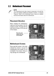
... other internal components of the AP130 server are already installed as indicated in section "1.4 Internal Features". Refer to the motherboard user's manual for detailed technical information about the motherboard.
Placement Direction
When installing the motherboard, make sure that you place it into the chassis correctly. The edge with the external ports goes to the rear part of the...
AP130 User Manual English Edition - Page 22

... Force (ZIF) socket on the P4B-MX motherboard supports an Intel Pentium 4 processor. This section tells you how to install a CPU. Refer to the motherboard user guide for more information.
CPU Socket Location
The CPU socket is located beside the rear panel connectors. Note the Pin 1 location on the socket.
Pin 1
CPU Orientation
A CPU has a mark (usually a notch or a gold mark...
AP130 User Manual English Edition - Page 23

... insert the CPU into the socket until it fits in place.
Gold Mark
Secure the CPU
When the CPU is in ...place, press it firmly on the socket while you push down the socket lever to secure the CPU. The lever clicks on the side tab to indicate that it is locked.
CAUTION
Incorrect installation of the CPU into the socket may bend the pins and severely damage the CPU!
ASUS AP130...
AP130 User Manual English Edition - Page 24

...retention module base. Make sure that the arrow on the bracket points inward.
2. Follow step 1 to install the other bracket.
3. When attached to the module base, flip the brackets sideways to allow enough room... base
NOTE
The retention module base is already installed on the motherboard upon purchase. Some CPU fan heatsink packages may also come with an extra module base.
24
Chapter 2: ...
AP130 User Manual English Edition - Page 26

...Install System Memory
DIMM Sockets Location
The motherboard has three Dual Inline Memory Module (DIMM) sockets that support 3.3V SDRAM modules in 32, 64, 128, 256, 512MB, or 1GB densities for up to 3GB system memory.
DIMM sockets
Install...snap back in place and the DIMM is properly seated.
DIMM Notch
Socket Break
Installed DIMM
CAUTION
DIMMs are keyed with notches so that they fit in only one ...
AP130 User Manual English Edition - Page 27
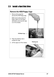
2.5 Install a Hard Disk Drive
Remove the HDD/Floppy Cage
1. Remove the screw that secures the HDD/floppy cage. Make sure to disconnect the floppy cable from the floppy disk before removing the cage out of the chassis.
HDD Metal Cage
2. Press the retaining clip to release the cage.
3. Lift the cage out of the chassis.
Retaining clip
ASUS AP130 Pedestal Server
27
AP130 User Manual English Edition - Page 28
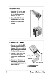
... the cable with Pin 1 on the IDE connector.
2. Connect a power cable (plug marked P5) to the power connector at the back of the drive.
Red Stripe to Pin 1 IDE Cable
3. Connect the other end of the IDE cable to the primary IDE connector (blue connector) on the motherboard.
Power Cable (P5)
To primary IDE connector on the motherboard
28
Chapter 2: Hardware Setup
AP130 User Manual English Edition - Page 29

2.6 Replace the Cover
Re-install the Cover
1. Position the cover in place, aligning the tabs on the inner side of the cover to the rail holes on the chassis edge.
2. Slide the cover toward the front panel until it fits in place. 3. Turn the thumbscrews to secure the cover to the chassis.
ASUS AP130 Pedestal Server
29
AP130 User Manual English Edition - Page 32

3.1 Getting Started
Make sure that you have completed the basic system installations in Chapter 2, then follow these steps to start up the server.
Connect a Monitor
Connect a monitor by plugging hte monitor cable to the video port (blue port) on the server rear panel.
Video Port
Connect the Power Cord
1. Adjust the voltage selector to the correct voltage...
AP130 User Manual English Edition - Page 38

... does not work
Check the mouse cable if properly connected to the mouse port.
The system does not perform power-on self tests (POST) after it was turned on
1. Check the memory modules and make sure you installed the DIMMs the system supports.
2. Make sure that the DIMMs are properly installed on the sockets.
38
Appendix B: Troubleshooting
AP130 User Manual English Edition - Page 39

... properly installed on the sockets.
Check if bootable HDD is active.
Onboard IDE HDD is unstable
Network connection not available
Install the utility drivers from the support CD that came with the package.
1. Make sure the network cable is connector the RJ-45 port on the rear panel.
2. Make sure that you have installed the network drivers from the motherboard support CD.
ASUS AP130 Pedestal...